
Install Instructions

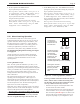


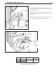
Table Of Contents
- Cover
- Table of Contents
- Table of Contents, Page 2
- Section 1 -GENERAL INFORMATION
- Section 2 -LOCATING THE APPLIANCE
- Section 3 -VENTING AND COMBUSTION AIR
- Section 4 -GAS SUPPLY AND PIPING
- Section 5 -PUMP REQUIREMENTS
- Section 6 -WATER CONNECTIONS -NTH BOILER
- Section 7 -ELECTRICAL AND WIRING DIAGRAMS
- Section 8 -THE USER INTERFACE
- 8.1 About the User Interface
- 8.2 Navigating the User Interface
- 8.3 The Home Display
- 8.4 Customizing your Home Display
- 8.5 Entering/Changing Control Settings
- 8.6 Quick Start
- Configuration and Setup
- 8.7 24 VAC Transformerwith Integral Circuit Breaker
- 8.8 Hydronic Heating Demand
- 8.9 Anti-Short-Cycle (ASC)
- 8.10 Outdoor Air Temperature Sensor
- 8.11 Outdoor Reset
- 8.12 Warm Weather Shutdown
- 8.13 Domestic Hot Water
- 8.14 About Lead Lag Operation
- 8.15 Adjusting CO2
- Section 9 -FIRST START-UP AND ADJUSTMENTINSTRUCTIONS
- Section 10 -MAINTENANCE
- Section 11 -OPERATING DETAILS AND TROUBLESHOOTING
- Section 12 -REPLACEMENT PARTS
- Appendix A -SOFTWARE CONTROL FUNCTIONS. Next 5 pages
- Appendix B -ERROR MESSAGES. Next 8 pages
- Back Cover. Contact information. Product and Service Videos

Page 45
NEOTHERM Residential Boilers
Table20. Residential,sizes80-210Mbtu,
CO
2
RangeandDifferentialPressure
GAS TYPE HIGH FIRE, CO
2
LOW FIRE, CO
2
DIFFRNTL PRESSURE
(incheswc)
Natural 8.8 to 9.8% 0.5% lower than
3.6” to 3.9”
Propane 9.8 to 10.2%
high re setting
The Gas Valve in the 80 thru 210 is at the front of the
unit and can be reached after the front panel is pulled
forward and then off.
Always be patient with your combustion analyzer when
making adjustments to the valve at both Hi-Fire and
Low-Fire.
Be sure to put the cap back onto the valve when you are
done making your adjustments at the gas valve.
under
cap
Gas Pressure Tap
Figure 36. -NeoThermGasValve80-210Mbtu