
Install Instructions
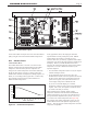
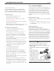

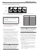


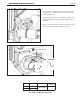
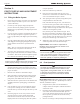
Table Of Contents
- Cover
- Table of Contents
- Table of Contents, Page 2
- Section 1 -GENERAL INFORMATION
- Section 2 -LOCATING THE APPLIANCE
- Section 3 -VENTING AND COMBUSTION AIR
- Section 4 -GAS SUPPLY AND PIPING
- Section 5 -PUMP REQUIREMENTS
- Section 6 -WATER CONNECTIONS -NTH BOILER
- Section 7 -ELECTRICAL AND WIRING DIAGRAMS
- Section 8 -THE USER INTERFACE
- 8.1 About the User Interface
- 8.2 Navigating the User Interface
- 8.3 The Home Display
- 8.4 Customizing your Home Display
- 8.5 Entering/Changing Control Settings
- 8.6 Quick Start
- Configuration and Setup
- 8.7 24 VAC Transformerwith Integral Circuit Breaker
- 8.8 Hydronic Heating Demand
- 8.9 Anti-Short-Cycle (ASC)
- 8.10 Outdoor Air Temperature Sensor
- 8.11 Outdoor Reset
- 8.12 Warm Weather Shutdown
- 8.13 Domestic Hot Water
- 8.14 About Lead Lag Operation
- 8.15 Adjusting CO2
- Section 9 -FIRST START-UP AND ADJUSTMENTINSTRUCTIONS
- Section 10 -MAINTENANCE
- Section 11 -OPERATING DETAILS AND TROUBLESHOOTING
- Section 12 -REPLACEMENT PARTS
- Appendix A -SOFTWARE CONTROL FUNCTIONS. Next 5 pages
- Appendix B -ERROR MESSAGES. Next 8 pages
- Back Cover. Contact information. Product and Service Videos

Page 44
LAARS Heating Systems
Control Settings for Lead Lag System - Part 2
1. On the Lead Lag Master, set the setpoint used by the Lead
Lag system.
How to get there: From the “Home” screen, press “I” to
go to “Info/Install.” Choose “Advanced Setup,” then go
to “Lead/ Lag Conguration.” Select “Lead Lag Master
Conguration,” and go to the line for “Setpoint.”
2. On the Lead Lag Master, set the Base Load to match
the number of boilers in the system. We mentioned the
Base Load setting in the explanation of the “Lead Lag
Modulation Cycle.” Whenever the heating demand causes
the active burner(s) to run faster than the Base Load value,
the Lead Lag system will put an additional burner on line.
The Base Load value depends on the number of boilers in
the system:
Note that you only need to enter the Base Load value on the
Lead Lag Master.
How to get there: From the “Home” screen, press “I” to
go to “Info/Install.” Choose “Advanced Setup,” then go
to “Lead/ Lag Conguration.” Select “Lead Lag Master
Conguration.” Go to the line for “Base Load Common
Rate.”
8.14 AboutLeadLagOperation
(continued)
8.15 Adjusting CO
2
1. Measure the CO
2
/O
2
in the ue products at high re.
The NeoTherm can be forced to high re to allow for
easier setup. The controller has a feature that makes it
easy to go directly to the high re condition. The unit
will operate at high re for 5 minutes, then modulate
down automatically.
How to get there: From the “Home” screen,
press “I” to go to “Info/ Install.” Choose “Test,” then
go to “Forced Rate.” Select “Set High Fire,” then
select “Start Test.”
The CO
2
readings should be between the values shown
in Table 20. If the CO
2
is not within the range shown,
adjustments may be made. To adjust the high re CO
2
,
locate the high re adjuster screw according to the
appropriate gure. Slowly make adjustments in 1/16
of a revolution increments until the CO
2
is within the
range identied.
2. Measure the CO
2
/O
2
in the ue products at low re.
NeoTherm can be forced to low re to allow for easier
setup.
How to get there: From the “Home” screen, press
“I” to go to “Info/ Install.” Choose “Test,” then go
to “Forced Rate.” Select “Set High Fire,” then select
“Start Test.”
The CO
2
readings should be between the values shown
in Table 20. If the CO
2
is not within the range shown,
adjustments may be made. To adjust the low re CO
2
,
locate the low re adjuster screw according to the
appropriate gure. Slowly make adjustments in 1/16
of a revolution increments until the CO
2
is within the
range identied.
3. Repeat steps 1 and 2 to conrm that the CO
2
ranges are
within the required ranges. Adjust if necessary.
4. Conrm that the differential pressure is still within the
appropriate range.
5. If any of the measurements cannot be adjusted
to the specied ranges or the CO levels are above
150ppm when adjusted, please consult the factory
for further information.
WARNING
Improper adjustment may lead to poor combustion
quality, increasing the amount of carbon monoxide
produced. Excessive carbon monoxide levels may
lead to personal injury or death.