
Install Instructions
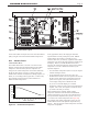
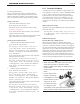

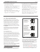
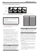


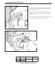
Table Of Contents
- Cover
- Table of Contents
- Table of Contents, Page 2
- Section 1 -GENERAL INFORMATION
- Section 2 -LOCATING THE APPLIANCE
- Section 3 -VENTING AND COMBUSTION AIR
- Section 4 -GAS SUPPLY AND PIPING
- Section 5 -PUMP REQUIREMENTS
- Section 6 -WATER CONNECTIONS -NTH BOILER
- Section 7 -ELECTRICAL AND WIRING DIAGRAMS
- Section 8 -THE USER INTERFACE
- 8.1 About the User Interface
- 8.2 Navigating the User Interface
- 8.3 The Home Display
- 8.4 Customizing your Home Display
- 8.5 Entering/Changing Control Settings
- 8.6 Quick Start
- Configuration and Setup
- 8.7 24 VAC Transformerwith Integral Circuit Breaker
- 8.8 Hydronic Heating Demand
- 8.9 Anti-Short-Cycle (ASC)
- 8.10 Outdoor Air Temperature Sensor
- 8.11 Outdoor Reset
- 8.12 Warm Weather Shutdown
- 8.13 Domestic Hot Water
- 8.14 About Lead Lag Operation
- 8.15 Adjusting CO2
- Section 9 -FIRST START-UP AND ADJUSTMENTINSTRUCTIONS
- Section 10 -MAINTENANCE
- Section 11 -OPERATING DETAILS AND TROUBLESHOOTING
- Section 12 -REPLACEMENT PARTS
- Appendix A -SOFTWARE CONTROL FUNCTIONS. Next 5 pages
- Appendix B -ERROR MESSAGES. Next 8 pages
- Back Cover. Contact information. Product and Service Videos

Page 43
NEOTHERM Residential Boilers
Figure 34. -Lead/LagOperation,3boilers. Figure 35. -Lead/LagOperation,4ormoreboilers.
Low demand -
The first boiler in
sequence fires at
less than 65%
First
boiler
Second
boiler
Third
boiler
Fourth
boiler
Demand increases -
Once the first boiler
reaches 65%,
the second boiler
switches on, and
both modulate
together between 20%
and 65% (this can be adjusted up to 25% to 85%).
Demand increases -
Once the first two
boilers reach 65%,
the third boiler
switches on, and all
three modulate together
between 20% and 65%
Nearing max. demand -
The fourth boiler is
active. Once all four
reach 65%, all are
allowed to go over
65%
* - The Lead/Lag controller will change the firing order of the boilers,
based on the run time of each burner.
Low demand -
The first boiler in
sequence fires at
less than 65%
First
boiler
Second
boiler
Third
boiler
Demand increases -
Once the first boiler
reaches 65%,
the second boiler
switches on, and
both modulate
together between 25%
and 65% (this adjustable up to 25% and 85%)
Demand increases -
Once the first two
boilers reach 65%,
the third boiler
switches on, and all
three modulate together
between 25% and 65%
Nearing max. demand -
Once all three reach
65%, then all three
are allowed to go over
65%
* - The Lead/Lag controller will change the firing order of the boilers,
based on the run time of each burner.
• On all of the boilers (including the Lead Lag Master),
identify each unit as a Follower by turning on “Follower
Enable.”
How to get there: From the “Home” screen, press “I”
to go to “Info/Install.” Choose “Advanced Setup,” then
go to “Lead/ Lag Conguration”. Select “Lead Lag
Follower Conguration.” On the line for “Follower
Enable” select “Enable.” When you select Follower
Enable these options will be displayed
“Enable via Modbus Master” or
“Enable via Sola Master”.
Choose “Enable via Sola Master”.
Wiring Connections for Lead Lag -
Now you can make the Modbus wiring connections
between the units. The controller in each boiler includes
two wiring terminals for the Modbus system, labeled
“MB1” and “MB2.” MB1 has the wiring connections to
the User Interface display on each unit, and MB2 is used
to communicate with the other boilers in the Lead Lag
system. See Figure 17.
To reach the controller, open the cabinet of the boiler by
removing the plastic bezel.
The wiring from the controller on the rst boiler runs to
the controller on the next boiler. Use 22 AWG or thicker
shielded twisted-pair wire with drain. Two twisted pairs
or three conductors are needed. Wire A on MB2 of Boiler
1 must be connected to A on MB2 of Boiler 2, wire B on
Boiler 1 goes to B on Boiler 2, and wire C on Boiler 1
goes to C on Boiler 2. Repeat this wiring for any other
boilers in the system. Connect all of the drain wires and
ground the drain wire on one end of the assembly only.