
Install Instructions
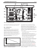
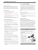

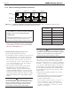


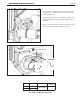
Table Of Contents
- Cover
- Table of Contents
- Table of Contents, Page 2
- Section 1 -GENERAL INFORMATION
- Section 2 -LOCATING THE APPLIANCE
- Section 3 -VENTING AND COMBUSTION AIR
- Section 4 -GAS SUPPLY AND PIPING
- Section 5 -PUMP REQUIREMENTS
- Section 6 -WATER CONNECTIONS -NTH BOILER
- Section 7 -ELECTRICAL AND WIRING DIAGRAMS
- Section 8 -THE USER INTERFACE
- 8.1 About the User Interface
- 8.2 Navigating the User Interface
- 8.3 The Home Display
- 8.4 Customizing your Home Display
- 8.5 Entering/Changing Control Settings
- 8.6 Quick Start
- Configuration and Setup
- 8.7 24 VAC Transformerwith Integral Circuit Breaker
- 8.8 Hydronic Heating Demand
- 8.9 Anti-Short-Cycle (ASC)
- 8.10 Outdoor Air Temperature Sensor
- 8.11 Outdoor Reset
- 8.12 Warm Weather Shutdown
- 8.13 Domestic Hot Water
- 8.14 About Lead Lag Operation
- 8.15 Adjusting CO2
- Section 9 -FIRST START-UP AND ADJUSTMENTINSTRUCTIONS
- Section 10 -MAINTENANCE
- Section 11 -OPERATING DETAILS AND TROUBLESHOOTING
- Section 12 -REPLACEMENT PARTS
- Appendix A -SOFTWARE CONTROL FUNCTIONS. Next 5 pages
- Appendix B -ERROR MESSAGES. Next 8 pages
- Back Cover. Contact information. Product and Service Videos

Page 37
NEOTHERM Residential Boilers
Connect the outdoor air temperature sensor to terminal block 7
(TB7), using the connections labeled Outdoor Temp Sensor.
8.11 Outdoor Reset
About Outdoor Reset -
The Outdoor Reset feature calculates a correction for the
hydronic (Central Heat) setpoint depending on the outdoor
temperature. This allows the system to compensate for
changes in the outdoor temperature and run more efciently.
(If the unit will operate as part of a Lead Lag system, the
Outdoor Reset function will adjust the Lead Lag setpoint. For
details, see “Cascading Lead Lag Operation” - Section 8.14.)
The graph below shows how the system will behave at
different outdoor temperatures:
22 27 32 37 42 47 52 57 62 67 72
77
90
100
110
120
130
140
Setpoint
Outdoor Temperature °F
Figure 30. –OutdoorResetOperation
In the graph shown above, the sloping line shows the
setpoint which is actually used by the system. Without
Outdoor Reset, this would be a constant 130°F (or
whatever other value you choose), regardless of the outdoor
temperature. The line in the graph would run straight across
the display. However, with the Outdoor Reset feature
turned on, the system will adjust for changes in the outdoor
temperature. Let’s take a detailed look at the way the
setpoint is adjusted.
• For cold outdoor temperatures (below 32°F), the setpoint
remains unchanged (130°F).
• As the temperature begins to rise above 32°F, the
Outdoor Reset function causes the setpoint to be lowered.
At these warmer temperatures, the heating load on the
system is not as great, so the system does not have to
reach as high a temperature to handle the load.
• As you can see from the display, at an outdoor
temperature of about 70°F, the system stops adjusting the
setpoint. Above 70°F, the setpoint is constant at 100°F
(or another value that you choose).
When Outdoor Reset is enabled, and the outdoor
temperature falls between the maximum and minimum
outdoor temperatures (70° and 32° in the example above),
the setpoint will be adjusted down by about .8° for every
1° increase in the outdoor temperature (See Figure 30).
For example, if the outdoor temperature rises by 10°, the
Outdoor Reset function will adjust the setpoint down by
about 5°. This ratio between outdoor temperature and water
temperature is adjustable.
Figure 31. -ControlPanelLayout