
Install Instructions
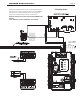

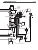

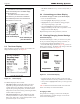
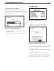
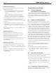
Table Of Contents
- Cover
- Table of Contents
- Table of Contents, Page 2
- Section 1 -GENERAL INFORMATION
- Section 2 -LOCATING THE APPLIANCE
- Section 3 -VENTING AND COMBUSTION AIR
- Section 4 -GAS SUPPLY AND PIPING
- Section 5 -PUMP REQUIREMENTS
- Section 6 -WATER CONNECTIONS -NTH BOILER
- Section 7 -ELECTRICAL AND WIRING DIAGRAMS
- Section 8 -THE USER INTERFACE
- 8.1 About the User Interface
- 8.2 Navigating the User Interface
- 8.3 The Home Display
- 8.4 Customizing your Home Display
- 8.5 Entering/Changing Control Settings
- 8.6 Quick Start
- Configuration and Setup
- 8.7 24 VAC Transformerwith Integral Circuit Breaker
- 8.8 Hydronic Heating Demand
- 8.9 Anti-Short-Cycle (ASC)
- 8.10 Outdoor Air Temperature Sensor
- 8.11 Outdoor Reset
- 8.12 Warm Weather Shutdown
- 8.13 Domestic Hot Water
- 8.14 About Lead Lag Operation
- 8.15 Adjusting CO2
- Section 9 -FIRST START-UP AND ADJUSTMENTINSTRUCTIONS
- Section 10 -MAINTENANCE
- Section 11 -OPERATING DETAILS AND TROUBLESHOOTING
- Section 12 -REPLACEMENT PARTS
- Appendix A -SOFTWARE CONTROL FUNCTIONS. Next 5 pages
- Appendix B -ERROR MESSAGES. Next 8 pages
- Back Cover. Contact information. Product and Service Videos

Page 33
NEOTHERM Residential Boilers
Quick Start This menu gives you an easy way to check or change the most common set-
tings on the unit:
• CH setpoint
• DHW setpoint
• Outdoor reset
• Low water temperature
• Maximum outdoor temperature
• Minimum outdoor temperature
• Adjustable high limit
• Adjustable low limit
See Section 8B for more information.
Login If you want to change a setup value or function, and the system requires a
password, you can enter it here. See the section on “Login Display.”
Test These parameters let you turn the burner on and off, and control the fan and
pump speeds. See the section on “Test Menu.”
Advanced Setup The sub-menus listed here allow you to set up most of the functions on the
controller. In the section on “Advanced Setup” we will explain how to reach all
of the setup functions. (For many of these functions, the system will require a
password before it will allow you to make changes.)
Diagnostics Use the Diagnostics to check the status of the sensors and the digital inputs
and outputs. The system also records a history of lockouts and alarms. See
the section on “Diagnostics.”
Display Setup You can use this option to adjust the contrast of the display or change the
items which appear at the top of the Home display. See the section on
Display Setup.
Table18. -FunctionsonInfo/InstallMenu
• Use the Up- and Down-Arrow buttons to step down
through the list until you have highlighted the correct line
on the display.
• Press the round OK button to select that line. Figure 22
shows a typical screen for this type of setting.
Figure 22. –ChangingaValue
• The current setting for the setpoint appears in the box at
the top of the screen. In this example, this is 182°F.
• The numbers near the left edge of the screen show the
allowable range for this value. In this case, the setpoint
can be set anywhere between 240°F and 32°F.
• Press the Up- and Down-Arrow buttons to scroll the
setpoint until you see the correct value in the box.
• When the value is correct, press the round OK button.
You will notice that the system did not ask you for a
password, so this is one of the values that can be changed
by anyone.
EnteringaTime
The controller uses several different timing functions, and
you can change some of these. (In this example, we will
use the screen for the Anti Short-Cycle Time.
Figure 23. -ChangingaTimingFunction