
Install Instructions
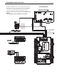

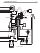

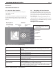
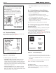
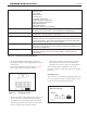
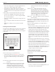
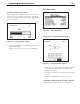
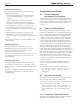
Table Of Contents
- Cover
- Table of Contents
- Table of Contents, Page 2
- Section 1 -GENERAL INFORMATION
- Section 2 -LOCATING THE APPLIANCE
- Section 3 -VENTING AND COMBUSTION AIR
- Section 4 -GAS SUPPLY AND PIPING
- Section 5 -PUMP REQUIREMENTS
- Section 6 -WATER CONNECTIONS -NTH BOILER
- Section 7 -ELECTRICAL AND WIRING DIAGRAMS
- Section 8 -THE USER INTERFACE
- 8.1 About the User Interface
- 8.2 Navigating the User Interface
- 8.3 The Home Display
- 8.4 Customizing your Home Display
- 8.5 Entering/Changing Control Settings
- 8.6 Quick Start
- Configuration and Setup
- 8.7 24 VAC Transformerwith Integral Circuit Breaker
- 8.8 Hydronic Heating Demand
- 8.9 Anti-Short-Cycle (ASC)
- 8.10 Outdoor Air Temperature Sensor
- 8.11 Outdoor Reset
- 8.12 Warm Weather Shutdown
- 8.13 Domestic Hot Water
- 8.14 About Lead Lag Operation
- 8.15 Adjusting CO2
- Section 9 -FIRST START-UP AND ADJUSTMENTINSTRUCTIONS
- Section 10 -MAINTENANCE
- Section 11 -OPERATING DETAILS AND TROUBLESHOOTING
- Section 12 -REPLACEMENT PARTS
- Appendix A -SOFTWARE CONTROL FUNCTIONS. Next 5 pages
- Appendix B -ERROR MESSAGES. Next 8 pages
- Back Cover. Contact information. Product and Service Videos

Page 32
LAARS Heating Systems
8.3 TheHomeDisplay
When the boiler is operating normally, the controller will
display the Home display. See Figure 20.
Figure 20. -HomeDisplay
The Home Display has three sections:
• The upper section (customizable) displays the most
important operating information for the unit. In the
example shown here, the display is showing the system
setpoint, the operating temperature, the outlet and inlet
temperatures for the water entering and leaving the boiler,
and the outdoor temperature.
• The central section shows some additional operating
and setup information. In this case, this area lists the
boiler name, boiler state, current demand, and the current
password level (the “access status”).
• The lower section shows any current lockouts, holds, or
alerts.
8.4 CustomizingyourHomeDisplay
To customize the upper section of your Home Display
• Press “I” Info/Install button
• Scroll to highlight “Display Setup”, press OK
• Highlight the line you would like to change,(example
”Line 2 Operating Temp”), press OK
• Scroll to highlight the parameter that you do want
displayed and then press OK. The new parameter is now
displayed on the Home Display.
Repeat this step for the other parameters, if desired.
8.5 Entering/ChangingControlSettings
Info/InstallDisplay
The Info/Install Display is where you will start every time.
All of your Controls, Diagnostics, Setups, and more, are
accessed starting with the Info/Display screen.
• From the Home display shown in Figure 20, press the “I”
button (“Info/ Install”). The display will change to show the
six sub-menus available. See Figure 21.
Figure 21. -Info/InstallDisplay
• To move from one choice to another, use the Left- and
Right-Arrow buttons or the Up- and Down-Arrow buttons.
• Once you have highlighted the choice you want, press the
round OK
Table 18 shows the functions listed under each of the sub-
menus. For details, see Sections 8A and 8C.
ChangingaValue
The procedure for changing a control value used by the
system is listed below. (In this example, we will use the
screen for the CH Setpoint.)
InstallOpManual
Doc#
1218G-NH.pdf
Doc#
1252-NH.pdf
(this
document)
The Neotherm ‘User Interface’ was updated
for the 2013 model year to the EMEA display
shown in Figure 27.
For older NeoTherms with the white
user inerface, you will need to download
the 1218G-NH.pdf from the ‘Discontinued
Documents’ on Laars.com.