
Install Instructions

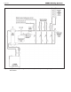


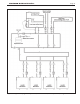

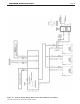


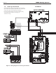
Table Of Contents
- Cover
- Table of Contents
- Table of Contents, Page 2
- Section 1 -GENERAL INFORMATION
- Section 2 -LOCATING THE APPLIANCE
- Section 3 -VENTING AND COMBUSTION AIR
- Section 4 -GAS SUPPLY AND PIPING
- Section 5 -PUMP REQUIREMENTS
- Section 6 -WATER CONNECTIONS -NTH BOILER
- Section 7 -ELECTRICAL AND WIRING DIAGRAMS
- Section 8 -THE USER INTERFACE
- 8.1 About the User Interface
- 8.2 Navigating the User Interface
- 8.3 The Home Display
- 8.4 Customizing your Home Display
- 8.5 Entering/Changing Control Settings
- 8.6 Quick Start
- Configuration and Setup
- 8.7 24 VAC Transformerwith Integral Circuit Breaker
- 8.8 Hydronic Heating Demand
- 8.9 Anti-Short-Cycle (ASC)
- 8.10 Outdoor Air Temperature Sensor
- 8.11 Outdoor Reset
- 8.12 Warm Weather Shutdown
- 8.13 Domestic Hot Water
- 8.14 About Lead Lag Operation
- 8.15 Adjusting CO2
- Section 9 -FIRST START-UP AND ADJUSTMENTINSTRUCTIONS
- Section 10 -MAINTENANCE
- Section 11 -OPERATING DETAILS AND TROUBLESHOOTING
- Section 12 -REPLACEMENT PARTS
- Appendix A -SOFTWARE CONTROL FUNCTIONS. Next 5 pages
- Appendix B -ERROR MESSAGES. Next 8 pages
- Back Cover. Contact information. Product and Service Videos

Page 25
NEOTHERM Residential Boilers
Figure 16. -ControlPanelLayout
7.5 OptionalFieldConnections
Terminal block 8 (TB8) in the control panel is used for the
‘Safety Chain’ and for connecting optional components such
as low water cutoffs, ow switches, additional high limits, and
other eld-supplied devices that must be interlocked with the
boiler. These are non-powered dry contacts only. All safeties
or end switches must be wired in series by removing the
supplied jumpers.
See Figure 16
7.4 HydronicHeatingUsingExternal
ModulationControl
About External Control -
When the NeoTherm is used for hydronic heating with
external modulation control, a call for heat must be supplied
to the “T-T or Interlock” terminal. Once the call is supplied
the control starts the Boiler and System pumps and begins the
ignition process. Once in Run, the NeoTherm monitors the
ame signal, call for heat, safeties, and water temperatures.
The boiler setpoint is used to limit the maximum water
temperature leaving the boiler only. The modulation rate
is controlled by a 4-20mA signal supplied by an external
control. (This can also be 0-10Vdc using a converter - Laars
part number CA006100.) When setting up a system using an
external control, take care to set Anti-Short Cycle feature to
prevent “hunting “ and possible premature component failure.