
Install Instructions
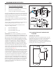

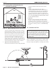

Table Of Contents
- Cover
- Table of Contents
- Table of Contents, Page 2
- Section 1 -GENERAL INFORMATION
- Section 2 -LOCATING THE APPLIANCE
- Section 3 -VENTING AND COMBUSTION AIR
- Section 4 -GAS SUPPLY AND PIPING
- Section 5 -PUMP REQUIREMENTS
- Section 6 -WATER CONNECTIONS -NTH BOILER
- Section 7 -ELECTRICAL AND WIRING DIAGRAMS
- Section 8 -THE USER INTERFACE
- 8.1 About the User Interface
- 8.2 Navigating the User Interface
- 8.3 The Home Display
- 8.4 Customizing your Home Display
- 8.5 Entering/Changing Control Settings
- 8.6 Quick Start
- Configuration and Setup
- 8.7 24 VAC Transformerwith Integral Circuit Breaker
- 8.8 Hydronic Heating Demand
- 8.9 Anti-Short-Cycle (ASC)
- 8.10 Outdoor Air Temperature Sensor
- 8.11 Outdoor Reset
- 8.12 Warm Weather Shutdown
- 8.13 Domestic Hot Water
- 8.14 About Lead Lag Operation
- 8.15 Adjusting CO2
- Section 9 -FIRST START-UP AND ADJUSTMENTINSTRUCTIONS
- Section 10 -MAINTENANCE
- Section 11 -OPERATING DETAILS AND TROUBLESHOOTING
- Section 12 -REPLACEMENT PARTS
- Appendix A -SOFTWARE CONTROL FUNCTIONS. Next 5 pages
- Appendix B -ERROR MESSAGES. Next 8 pages
- Back Cover. Contact information. Product and Service Videos

Page 13
NEOTHERM Residential Boilers
Section 4 -
GAS SUPPLY AND PIPING
All Installations must conform to the National Fuel Gas Code
ANSI Z223.1/NFPA54, and/or local codes. In Canada, the
installation must conform to the latest edition of CSA B149.1
Natural Gas and Propane Gas Installation Code, and/or local
codes. Gas piping should be supported by suitable hangers or
oor stands, not the appliance.
Review the following instructions before proceeding with the
installation.
1. Verify that the appliance is tted for the proper type of
gas by checking the rating plate. NeoTherm will function
properly without the use of high altitude modication at
elevations up to 10,000 feet (3050 m).
2. The maximum inlet gas pressure must not exceed 13”
W.C. (3.2kPa). The minimum inlet gas pressure is 4”
W.C. (1.0kPa).
3. Refer to Table 10 thru Table 13 to size the piping.
4. Run gas supply line in accordance with all applicable
codes.
5. Locate and install manual shutoff valves in accordance
with state and local requirements.
6. A sediment trap must be provided upstream of the gas
controls.
7. All threaded joints should be coated with piping
compound resistant to action of liqueed petroleum gas.
8. The appliance and its individual shutoff valve must be
disconnected from the gas supply piping during any
pressure testing of that system at test pressures in excess
of 1/2 PSIG (3.45kPa).
9. The unit must be isolated from the gas supply system by
closing its individual manual shutoff valve during any
pressure testing of the gas supply piping system at test
pressures equal to or less than 1/2 PSIG (3.45kPa).
10. The appliance and its gas connection must be leak tested
before placing it in operation.
11. Purge all air from gas lines.
WARNING:
Open ame can cause gas to ignite and result in
property damage, severe injury, or loss of life.
At the time of removal of an existing boiler, the following
steps shall be followed with each appliance remaining
connected to the common venting system placed in operation,
while the other appliances remaining connected to the
common venting system are not in operation.
1. Seal any unused openings in the common venting
system.
2. Visually inspect the venting system for proper size and
horizontal pitch and determine there is no blockage or
restriction, leakage, corrosion and other deciencies
which could cause an unsafe condition.
3. Insofar as it is practical, close all building doors and
windows and all doors between the space in which the
appliances remaining connected to the common venting
system are located and other spaces of the building. Turn
on clothes dryers and any appliance not connected to
the common venting system. Turn on any exhaust fans,
such as range hoods and bathroom exhausts, so they will
operate at maximum speed. Do not operate a summer
exhaust fan. Close replace dampers.
4. Place in operation the appliance being inspected. Follow
the lighting instructions. Adjust the thermostat so the
appliance will operate continuously.
5. Test for spillage at the draft hood relief opening after
5 minutes of main burner operation. Use the ame of a
match or candle, or smoke from a cigarette, cigar or pipe.
6. After it has been determined that each appliance
remaining connected to the common venting system
properly vents when tested as outlined above, return
doors, windows, exhaust fans, replace dampers and any
other gas burning appliance to their previous conditions
of use.
7. Any improper operation of the common venting system
should be corrected so that the installation conforms to
the National Fuel Gas Code, ANSI Z223.1/NFPA 54 and/
or CSA B149.1, Installation Codes. When resizing any
portion of the common venting system, the common
venting system should be resized to approach the mini-
mum size as determined using the appropriate tables and
guidelines in the National Fuel Gas Code, ANSI Z223.1
NFPA 54 and/or CSA B149.1, Installation Codes.
NOTE: The NeoTherm appliance and all other gas
appliances sharing the gas supply line must be ring
at maximum capacity to properly measure the inlet
supply pressure. The pressure can be measured at
the supply pressure port on the gas valve. Low gas
pressure could be an indication of an undersized
gas meter, undersized gas supply lines and/or an
obstructed gas supply line. Some NeoTherm units are
equipped with low and high pressure gas switches
that are integrally vent limited. These types of devices
do not require venting to atmosphere.