
Install Instructions
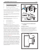

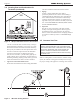

Table Of Contents
- Cover
- Table of Contents
- Table of Contents, Page 2
- Section 1 -GENERAL INFORMATION
- Section 2 -LOCATING THE APPLIANCE
- Section 3 -VENTING AND COMBUSTION AIR
- Section 4 -GAS SUPPLY AND PIPING
- Section 5 -PUMP REQUIREMENTS
- Section 6 -WATER CONNECTIONS -NTH BOILER
- Section 7 -ELECTRICAL AND WIRING DIAGRAMS
- Section 8 -THE USER INTERFACE
- 8.1 About the User Interface
- 8.2 Navigating the User Interface
- 8.3 The Home Display
- 8.4 Customizing your Home Display
- 8.5 Entering/Changing Control Settings
- 8.6 Quick Start
- Configuration and Setup
- 8.7 24 VAC Transformerwith Integral Circuit Breaker
- 8.8 Hydronic Heating Demand
- 8.9 Anti-Short-Cycle (ASC)
- 8.10 Outdoor Air Temperature Sensor
- 8.11 Outdoor Reset
- 8.12 Warm Weather Shutdown
- 8.13 Domestic Hot Water
- 8.14 About Lead Lag Operation
- 8.15 Adjusting CO2
- Section 9 -FIRST START-UP AND ADJUSTMENTINSTRUCTIONS
- Section 10 -MAINTENANCE
- Section 11 -OPERATING DETAILS AND TROUBLESHOOTING
- Section 12 -REPLACEMENT PARTS
- Appendix A -SOFTWARE CONTROL FUNCTIONS. Next 5 pages
- Appendix B -ERROR MESSAGES. Next 8 pages
- Back Cover. Contact information. Product and Service Videos

Page 12
LAARS Heating Systems
a. In the event that the side-wall horizontally vented gas
fueled equipment is installed in a crawl space or an attic,
the hard-wired carbon monoxide with alarm and battery
back-up may be installed on the next adjacent oor level.
b. In the event that the requirements of the subdivision
cannot be met at the time of completion of installa-
tion, the owner shall have a period of thirty (30) days to
comply with the above requirements, provided, however,
that during said thirty (30) day period, a battery operated
carbon monoxide detector with an alarm be installed.
2. Approved Carbon Monoxide Detectors
Each carbon monoxide detector shall comply with NFPA
720 and be ANSI/UL 2034 listed and IAS certied.
3. Signage
A metal or plastic identication plate shall be
permanently mounted to the exterior of the building at
a minimum height of eight (8) feet above grade directly
in line with the exhaust vent terminal for horizontally
vented gas fueled heating appliance or equipment. The
sign shall read, in print no less than one-half (1/2) inch in
size: “GAS VENT DIRECTLY BELOW, KEEP CLEAR
OF ALL OBSTRUCTIONS.”
4. Inspection
The state or local gas inspector of the side-wall hori-
zontally vented gas fueled appliance shall not approve
the installation unless, upon inspection, the inspector
observes carbon monoxide detectors and signage installed
in accordance with the provisions of 248 CMR 5.08(2)
(a) 1-4.
3.5 Common Vent Test
NOTE: This section does not describe a method for
common venting NeoTherm units. It describes what
must be done when a unit is removed from a common
vent system. NeoTherm units require special vent
systems and fans for common vent. Contact the
factory if you have questions about common venting
NeoTherm units.
When an existing boiler is removed from a common venting
system, the common venting system is likely to be too large
for proper venting of the appliances remaining connected to it.
Figure 7. -MinimumVentingDistance
Figure 8. -MultipleSide-WallTerminals,AirandVent
3.4 LocatingVentandCombustionAir
Terminals(continued)