
Install Instructions
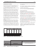
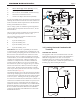
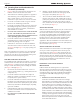

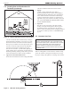

Table Of Contents
- Cover
- Table of Contents
- Table of Contents, Page 2
- Section 1 -GENERAL INFORMATION
- Section 2 -LOCATING THE APPLIANCE
- Section 3 -VENTING AND COMBUSTION AIR
- Section 4 -GAS SUPPLY AND PIPING
- Section 5 -PUMP REQUIREMENTS
- Section 6 -WATER CONNECTIONS -NTH BOILER
- Section 7 -ELECTRICAL AND WIRING DIAGRAMS
- Section 8 -THE USER INTERFACE
- 8.1 About the User Interface
- 8.2 Navigating the User Interface
- 8.3 The Home Display
- 8.4 Customizing your Home Display
- 8.5 Entering/Changing Control Settings
- 8.6 Quick Start
- Configuration and Setup
- 8.7 24 VAC Transformerwith Integral Circuit Breaker
- 8.8 Hydronic Heating Demand
- 8.9 Anti-Short-Cycle (ASC)
- 8.10 Outdoor Air Temperature Sensor
- 8.11 Outdoor Reset
- 8.12 Warm Weather Shutdown
- 8.13 Domestic Hot Water
- 8.14 About Lead Lag Operation
- 8.15 Adjusting CO2
- Section 9 -FIRST START-UP AND ADJUSTMENTINSTRUCTIONS
- Section 10 -MAINTENANCE
- Section 11 -OPERATING DETAILS AND TROUBLESHOOTING
- Section 12 -REPLACEMENT PARTS
- Appendix A -SOFTWARE CONTROL FUNCTIONS. Next 5 pages
- Appendix B -ERROR MESSAGES. Next 8 pages
- Back Cover. Contact information. Product and Service Videos

Page 9
NEOTHERM Residential Boilers
E. CPVC exhaust pipe section (80-210) (not incl.)
F. outdoor/system sensor kit
G. ow switch kit (399-850MBH, Commercial Only)
H. alternate size vent/terminal screens
J. exhaust vent adapter CPVC/ST ST (750-850)
It is the responsibility of the appropriately licensed technician
installing this NeoTherm unit to use ULC S636 certied vent
material consistent with the requirements as described in the
Venting and Combustion Air section.
Class I venting systems are suitable for gas-red appliances
producing ue gas temperature of more than 135°C, but not
more than 245°C.
Class II venting systems are suitable for gas-red appliances
producing ue gas temperatures of 135°C or less.
Class II venting systems are further classied into four
temperature ratings as follows:
A Up to and including 65°C
B Up to and including 90°C
C Up to and including 110°C, and
D Up to and including 135°C
IMPORTANT! It is also the responsibility of the installer
to ensure that a ue gas sampling port is installed in the vent
system. This ue gas sampling port must be installed near the
ue connection of the NeoTherm unit: within 2 feet of the
ue connection. There is no ue gas sampling port internal
to the NeoTherm, so one must be installed in the vent system
external to the NeoTherm unit. A ue gas sampling port
available as a component of the ULC S636 certied vent
system is preferred. However, if one is not available with
the certied vent system, Laars suggests using a tee with the
branch connection sized to allow for insertion of a ue gas
analyzer probe. The branch connection must be resealable
with a cap or other by other means to ensure the vent system
remains sealed. (See Figure 5.)
Consideration must be given to the placement and orientation
of the ue gas sampling port to ensure that condensate is free
to ow back into the NeoTherm unit and not collect anywhere
in the vent system - including in the ue gas sampling port.
An exhaust vent terminal must be installed. If an exhaust vent
terminal is not available with the certied vent system, Laars
suggests the use of a coupler tting from the certied vent
system into which the vent terminal screen, included with the
NeoTherm and shown in the Unpacking section, be installed.
Be sure to install and terminate both vent and combustion
air pipes per the Venting and Combustion Air section of the
NeoTherm instructions.
3.4 LocatingVentandCombustionAir
Terminals
SideWallVentTerminal
The appropriate side wall vent terminal must be used. The
terminal must be located in accordance with ANSI Z223.1/
NFPA 54 and applicable local codes. In Canada, the
installation must be in accordance with CSA B149.1 or .2
and local applicable codes. Consider the points listed on the
following page when installing the terminal.
Figure 5. -TestPort-ULC-S636system
Figure 4. -CombustionAirandVentThroughRoof
*
*
*
*
*
*
*
In Canada, refer to CAN/CSA B199.1