
Install Instructions
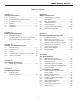
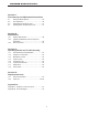
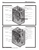


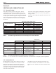
Table Of Contents
- Cover
- Table of Contents
- Table of Contents, Page 2
- Section 1 -GENERAL INFORMATION
- Section 2 -LOCATING THE APPLIANCE
- Section 3 -VENTING AND COMBUSTION AIR
- Section 4 -GAS SUPPLY AND PIPING
- Section 5 -PUMP REQUIREMENTS
- Section 6 -WATER CONNECTIONS -NTH BOILER
- Section 7 -ELECTRICAL AND WIRING DIAGRAMS
- Section 8 -THE USER INTERFACE
- 8.1 About the User Interface
- 8.2 Navigating the User Interface
- 8.3 The Home Display
- 8.4 Customizing your Home Display
- 8.5 Entering/Changing Control Settings
- 8.6 Quick Start
- Configuration and Setup
- 8.7 24 VAC Transformerwith Integral Circuit Breaker
- 8.8 Hydronic Heating Demand
- 8.9 Anti-Short-Cycle (ASC)
- 8.10 Outdoor Air Temperature Sensor
- 8.11 Outdoor Reset
- 8.12 Warm Weather Shutdown
- 8.13 Domestic Hot Water
- 8.14 About Lead Lag Operation
- 8.15 Adjusting CO2
- Section 9 -FIRST START-UP AND ADJUSTMENTINSTRUCTIONS
- Section 10 -MAINTENANCE
- Section 11 -OPERATING DETAILS AND TROUBLESHOOTING
- Section 12 -REPLACEMENT PARTS
- Appendix A -SOFTWARE CONTROL FUNCTIONS. Next 5 pages
- Appendix B -ERROR MESSAGES. Next 8 pages
- Back Cover. Contact information. Product and Service Videos

Page 6
LAARS Heating Systems
Table5. -AllowableSingleWallStainlessSteelVentSuppliersandPartNumbers.
Table6. -AllowablePolypropyleneVentManufacturers/TradeNames
Section 3 -
VENTING AND COMBUSTION AIR
3.1 GeneralVenting
This product requires a special venting system. Refer to
venting supplier’s instructions for complete parts list and
method of installation. The manufacturers and product lines
listed on the following tables have been tested and authorized
to safely operate with Laars equipment. Suppliers of stainless
steel and polypropylene venting that are not listed on these
tables are not permitted for use with Laars vent category III/
IV products.
NOTE: 1. “x”, “xx”, and “xxxx” refer to variations in nominal size. See manufacturer’s catalog for a particular application.
Do not mix venting suppliers and models in venting systems.
Failure to comply could result in personal injury, property
damage, or death.
Installations must comply with applicable national, state and
local codes.
ALLOWABLE SINGLE WALL STAINLESS STEEL VENT SUPPLIERS AND PART NUMBERS
Selkirk
DuraVent
NovaFlex
Safe-TVentEZSeal FasNSeal Z Flex
90° Elbow 9x14 FSELB90xx 2SVEExx90
Pipe 9x07 FSVLxxxx 2SVEPxxxx
Boiler Adapter 5x01BOI FSAAUx
2SVSAxx (OD)
2SVSTTAxx (ID)
Horizontal Termination (bird screen
9x92 FSBSx 2SVSTPXxx
Vertical Termination (rain cap) 5X00CI FSRCx 2SVSRCxx
Inlet Air Termination 9xTERM FSAIHXX* 2SVSTEXxx90
Adapter, SS to CPVC FSA-xxFNSM-xPVCF
Adapter SS to PP FSAAUx-xPP 2ZDCPVCx**
*4", 6" & 7" only **up to 6"
ALLOWABLE POLYPROPYLENE VENT MANUFACTURERS / TRADE NAMES
CentroTherm DuraVent
Selkirk
NovaFlex
InnoFlue PolyPro
PolyFlue
Z-Dens
Single Wall Pipe ISVLxxxx xPPS-x 83x002 ZDPx
Elbow ISELxxxx xPPS-E90L 83x08 2ZDEx87
PVC Adapter ISAGLxxxx
xPPS-ADL (to 4")
xPPS-xxPVCM-xPPF (>4")
83x040 2ZDCPVCx
Horizontal Termination
(bird screen)
IASPPxx (2" - 4")
IASSSxx (5" - 12")
xPPS-BG (2" - 6")
83x050 2ZDESx
Vertical Termination
IASPPxx (2" - 4")
IASSSxx (5" - 12")
xPPS-VKL (<5")
xPPS-VTML (5"-8")
83x050 2ZDESx
Air Inlet 2ZDESx
MFR MODEL NUMBER (ABBREVIATED)
MFR MODEL NUMBER (ABBREVIATED)
Trade Name / Model
ExampleComponents
ExampleComponents
Trade Name / Model
3.2 CombustionAir
NeoTherm boilers and water heaters must have provisions
for combustion and ventilation air in accordance with the
applicable requirements for Combustion Air Supply and
Ventilation in the National Fuel Gas Code, ANSI Z223 1; or
in Canada, the Natural Gas and Propane Installation Code,
CSA B149.1. All applicable provisions of local building
codes must also be adhered to.
A NeoTherm unit can take combustion air from the space
in which it is installed, or the combustion air can be ducted
directly to the unit. Ventilation air must be provided in either
case.