
Install Instructions


LAARS Heating Systems
Page 30
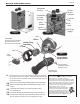
4.13 Gas Conversion Kit
Customer Service and Product Support: 800.900.9276 • Fax 800.559.1583
Headquarters: 20 Industrial Way, Rochester, NH, USA 03867 • 603.335.6300 • Fax 603.335.3355
1869 Sismet Road, Mississauga, Ontario, Canada L4W 1W8 • 905.238.0100 • Fax 905.366.0130
www.Laars.com Litho in U.S.A. © Laars Heating Systems 1607 Document 4286A
800.900.9276 • Fax 800.559.1583 (Customer Service, Service Advisors)
20 Industrial Way, Rochester, NH 03867 • 603.335.6300 • Fax 603.335.3355 (Applications Engineering)
1869 Sismet Road, Mississauga, Ontario, Canada L4W 1W8 • 905.238.0100 • Fax 905.366.0130
www.Laars.com
Document 4286A
M
ascot ST Gas Conversion Kit
pg 3 of 4
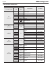
Table B DIP Switch Settings
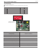
Figure D
15.
Per Table B, set DIP Switch
5 to OFF
for LP Propane
.
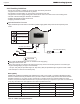
16.
Turn ON the GAS and WATER supply to the Mascot ST.
17.
Turn ON the Mascot ST.
NOTE: If your Mascot ST is installed at an altitude greater than
2,000 ft, then the correct altitude setting should have
been set previously and saved within the Control Display. If this has not been done, Refer to Section 4.12 of the
Mascot ST Install and Operating Manual (document #1316) before continuing with this Gas Conversion.
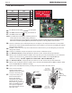
18.
Connect a manometer to the manifold pressure port. See Figure D. For dual port manometers, use the positive
pressure side. Check for proper manifold gas pressure. Refer to Table D. You must have acceptable gas manifold
pressure before continuing.
19.
Establish a call for heat. You may need to disconnect the outdoor reset if you are making this gas conversion
during warm weather.
20.
Setup your combustion analyser and place the sensor into the combustion test port.
21.
Per Table B for Max Fire
,
change dip switch 6 to ON and 7 to OFF. The unit will cycle up to MAX re.
22.
WAIT for your combustion analyser to stabilize. This may take up to 3 minutes depending on your combustion
analyser. Then check the CO
2
measurement for MAX re. Refer to Table C for acceptable MAX re
combustion readings Do NOT adjust CO2 at MAX Fire. ONLY in MIN Fire, so...
23.
Per Table B for MIN Fire
,
change dip switch 6 to OFF and 7 to ON. The unit will cycle down to MIN Fire.
24.
WAIT for your combustion analyser to stabilize. Then check the CO
2
measurement for MIN re. Refer to Table
D for acceptable MIN re combustion readings
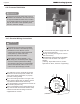
25.
Open the Gas Valve Adjustment Port by removing the cap screw with a 4mm Allen wrench.
ON OFF
#
MIN Fire Normal Operation 7
MAX Fire Normal Operation 6
NG Natural LP Propane 5
Inlet ow Over-ride ON Inlet ow Over-ride OFF 4
Normal Operation
Do Not Touch
3
Normal Operation
Do Not Touch
2
Normal Operation
Do Not Touch
1
+
-
Adjust CO
2
In MIN Fire only.
26.
Then use the 4 mm Allen
wrench to make a minor
adjustment (1/8 turn) to either
increase or decrease CO
2
.
27.
It may be necessary to go
back and forth between
HI Fire and LOW Fire
several times (and making
adjustments only at LOW
Fire), before CO
2
at both are
within acceptable levels. Be
sure to put the adjustment
port cap screw back onto the
valve when done.