
Install Instructions


LAARS Heating Systems
Page 26
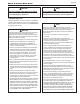
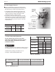
Manifold
pressure
port.
4.11 Gas Setup and Adjustment
For the Step by step process to measure
CO
2
values on the Mascot ST, please refer to
Step 16 thru Step 28 in Section 4.13 of this
Installation Manual.
Offset Fire
Adjustment
Screw
Adjust ONLY when in
MIN Fire and when
using a combustion
analyzer.
See Section 4.13 for
step by step details.
Inlet Gas
pressure port
Table 10. CO
2
Values
Table 12. Manifold Pressures
WARNING
Installer is required to verify combustion settings as part of
the installation process. CO should not exceed 300 ppm.
Standard Factory Setting is for MIN Fire. 9.0%
CO
2
@ 0 - 2,000 ft altitude (Natural Gas).
4.10 Gas Supply Pressure
Refer to the illustration. Check the gas inlet pressure
measurement from inlet gas pressure port.(Loosen the
port bolts before you check the gas inlet pressure.)
1. The appliance and its individual shutoff valve must
be disconnected from the gas supply piping system
during any pressure testing of that system at test
pressures in excess of 1/2 psi (3.5 kPa).
2. The appliance must be isolated from the gas supply
piping system by closing its individual manual shutoff
valve during any pressure testing of the gas supply
piping system at test pressures equal to or less than
1/2 psi (3.5 kPa).
Natural Gas LP Gas
Maximum
Pressure
10.5˝
WC
Maximum
Pressure
13.0˝
WC
Minimum
Pressure
3.5˝
WC
Minimum
Pressure
8.0˝
WC
Table 11. Min and Max Inlet Gas Line Pressures
Customer Service and Product Support: 800.900.9276 • Fax 800.559.1583
Headquarters: 20 Industrial Way, Rochester, NH, USA 03867 • 603.335.6300 • Fax 603.335.3355
1869 Sismet Road, Mississauga, Ontario, Canada L4W 1W8 • 905.238.0100 • Fax 905.366.0130
www.Laars.com Litho in U.S.A. © Laars Heating Systems 1607 Document 4286A
800.900.9276 • Fax 800.559.1583 (Customer Service, Service Advisors)
20 Industrial Way, Rochester, NH 03867 • 603.335.6300 • Fax 603.335.3355 (Applications Engineering)
1869 Sismet Road, Mississauga, Ontario, Canada L4W 1W8 • 905.238.0100 • Fax 905.366.0130
www.Laars.com
Document 4286A
Mascot ST Gas Conversion Kit
pg 4 of 4
Table C
Table D
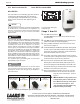
Figure E (Conversion label)
28.
Once the CO
2
for both MIN and MAX Fire are
acceptable per Table C, set DIP switches 6 and
7 to the OFF position for Nominal Fire (normal
operation).
29.
Write in the correct Conversion Date and the
Technicians Name to the included gas conversion
sticker. See Figure E. Then apply that sticker
adjacent to the rating plate.
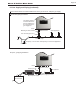
30.
Put the water heater cover back on and assemble/
tighten the 4 screws that hold the cover in place.
This unit was converted on ____/____/___to _____gas
with kit #____________by______________________
(name and company __________________________
accountable)_________________________________
___________________________________________
Cette unité a été converti ____/____/____ten ______gaz
en utilisant le kit numéro _____ par______________
(nom et société_________________________________
responsable)___________________________________
_____________________________________________
High Altitude
Setting level
‘LP’
CO
2
Values
‘NG’
CO
2
Values
MSTWW199
2" or 3" VENT 2" or 3" VENT
0~2,000 ft
10.7 MAX 10
9.7 MIN 8.5
2,000~5,000 ft
10.2 MAX 9.1
10.3 MIN 9.7
5,000~8,000 ft
10.3 MAX 9.1
10.4 MIN 9.8
8,000~10,000 ft
10.5 MAX 9
10.6 MIN 9.8
AVERTISSEMENT
Ce conversion doit être installé par un organisme de
service conformément aux instructions du fabricant
et tous les codes et les exigences de l’autorité
compétente. Si les informations contenues dans ces
instructions n’est pas suivi à la lettre, un incendie,
une explosion ou de la production de monoxyde
de carbone mais résultat causant des dommages
matériels, des blessures ou des pertes de vie. Le
service est responsable pour la bonne et complète
l’installation de ce kit. L’installation n’est pas correcte
et complète jusqu’à ce que le fonctionnement de
l’appareil converti est véri ée comme
spéci é dans
le manuel d’instruction fourni avec le
kit.
Manifold pressure ‘NG’ type combustibility ‘LP’ type combustibility
MSTWW199
MAX FIRE -0.11” to -0.17” WC -0.07” to -0.11” WC
MIN FIRE -0.10” to -0.16” WC -0.06” to -0.10” WC
H2373700A
Customer Service and Product Support: 800.900.9276 • Fax 800.559.1583
Headquarters: 20 Industrial Way, Rochester, NH, USA 03867 • 603.335.6300 • Fax 603.335.3355
1869 Sismet Road, Mississauga, Ontario, Canada L4W 1W8 • 905.238.0100 • Fax 905.366.0130
www.Laars.com Litho in U.S.A. © Laars Heating Systems 1607 Document 4286A
800.900.9276 • Fax 800.559.1583 (Customer Service, Service Advisors)
20 Industrial Way, Rochester, NH 03867 • 603.335.6300 • Fax 603.335.3355 (Applications Engineering)
1869 Sismet Road, Mississauga, Ontario, Canada L4W 1W8 • 905.238.0100 • Fax 905.366.0130
www.Laars.com
Document 4286A
Mascot ST Gas Conversion Kit
pg 4 of 4
Table C
Table D
Figure E (Conversion label)
28.
Once the CO
2
for both MIN and MAX Fire are
acceptable per Table C, set DIP switches 6 and
7 to the OFF position for Nominal Fire (normal
operation).
29.
Write in the correct Conversion Date and the
Technicians Name to the included gas conversion
sticker. See Figure E. Then apply that sticker
adjacent to the rating plate.
30.
Put the water heater cover back on and assemble/
tighten the 4 screws that hold the cover in place.
This unit was converted on ____/____/___to _____gas
with kit #____________by______________________
(name and company __________________________
accountable)_________________________________
___________________________________________
Cette unité a été converti ____/____/____ten ______gaz
en utilisant le kit numéro _____ par______________
(nom et société_________________________________
responsable)___________________________________
_____________________________________________
High Altitude
Setting level
‘LP’
CO
2
Values
‘NG’
CO
2
Values
MSTWW199
2" or 3" VENT 2" or 3" VENT
0~2,000 ft
10.7 MAX 10
9.7 MIN 8.5
2,000~5,000 ft
10.2 MAX 9.1
10.3 MIN 9.7
5,000~8,000 ft
10.3 MAX 9.1
10.4 MIN 9.8
8,000~10,000 ft
10.5 MAX 9
10.6 MIN 9.8
AVERTISSEMENT
Ce conversion doit être installé par un organisme de
service conformément aux instructions du fabricant
et tous les codes et les exigences de l’autorité
compétente. Si les informations contenues dans ces
instructions n’est pas suivi à la lettre, un incendie,
une explosion ou de la production de monoxyde
de carbone mais résultat causant des dommages
matériels, des blessures ou des pertes de vie. Le
service est responsable pour la bonne et complète
l’installation de ce kit. L’installation n’est pas correcte
et complète jusqu’à ce que le fonctionnement de
l’appareil converti est véri ée comme
spéci é dans
le manuel d’instruction fourni avec le
kit.
Manifold pressure ‘NG’ type combustibility ‘LP’ type combustibility
MSTWW199
MAX FIRE -0.11” to -0.17” WC -0.07” to -0.11” WC
MIN FIRE -0.10” to -0.16” WC -0.06” to -0.10” WC
H2373700A