Installation and Operation Instructions Document 1316B Installation and Operation Instructions for MASCOT ® ST Wall-Mounted, Modulating Gas Condensing Water Heater Model MSTWW 199,000 BTU/hr • Natural Gas (NG) - Factory Configuration • Propane Gas (LP) - Field-Convertible FOR YOUR SAFETY: This product must be installed and serviced by a professional service technician, qualified in hot water boiler and heater installation and maintenance.
LAARS Heating Systems SECTION 1 Product Accessories TABLE OF CONTENTS 1.1 Introduction........................................................... 1 4.17 Electrical Wiring Connections................................ 34 1.1 Included with the Appliance.................................... 1 4.18 DIP Switches..........................................................35 4.19 Control Board, Electrical Diagram ........................ 36 SECTION 2 Product Characteristics 4.20 Ladder Diagram..................
Page 1 Mascot ST Tankless Water Heater SECTION 1. Product Accessories 1.1 Introduction This manual provides information necessary for the installation, operation, and maintenance of the LAARS Heating Systems Mascot ST. All application and installation procedures must be read and reviewed completely before proceeding with the installation. Consult the LAARS Heating Systems factory, or your local factory representative, with any problems or questions regarding this equipment.
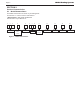
LAARS Heating Systems Page 2 SECTION 2. Product Characteristics 2.1 Model Nomenclature The Model Nomenclature is shown on your Rating Plate and consists of a series of letters and numbers ( Nomenclature ) that further identifies the characteristics of your Mascot ST. 1 2 3 4 5 6 7 8 9 10 11 12 13 M S T W W 1 9 9 A 1 X X W - Condensing Water Heater W - Wall Hung SERIES Mascot ST CONFIG Figure 1.
Page 3 Mascot ST Tankless Water Heater 2.2 Specifications Model Name MSTWW199 MAX 199,000 Btu/h MIN 19,900 Btu/h 35°F Rise 11.0 GPM 45°F Rise 8.5 GPM 77°F Rise 5.0 GPM Gas Input Rate Hot Water Capacity Installation Indoor Wall Hung Flue System Sealed Combustion Direct & Single Vnet Vent Run 2″(50ft) / 3″(100ft) Schedule 40 PVC, CPVC, PP, ABS Gas Supply Pressure Manifold Pressure Power Supply NG 3.5˝ WC to 10.5˝ WC LP 8.0˝ WC to 13.0˝ WC Gas Type NG LP MAX Fire -0.11” to -0.
LAARS Heating Systems Page 4 2.
Page 5 Mascot ST Tankless Water Heater Vent 2.
LAARS Heating Systems Page 6 SECTION 3. Safety Regulations 3.1 Safety Symbols WARNING To avoid product damage, personal injury, or even possible death, carefully read, understand, and follow all the instructions in the Installation and Operation manual before installation, operation and service the Water Heater. Laars cannot anticipate every circumstance that might involve a potential hazard. Therefore, all possible incidents are not included in our warnings.
Page 7 Mascot ST Tankless Water Heater damaging condition that might affect the operation of the unit. Water Heater must be checked by a qualified technician before resuming operation. DANGER Vapors from flammable liquids will explode and catch on fire. These will cause death or severe burns. Do not use or store flammable products such as gasoline, solvents or adhesives in the same room or area near the appliance.
LAARS Heating Systems Page 8 SECTION 3. Safety Regulations 3.2 Safety Precautions and Proper Use When in Operation Before Operation 1. Check the Gas Type (NG/LP) When using or moving the unit for the first time, check if gas type matches with the gas type of the Water Heater. Check whether the gas type which is supplied is NG (Natural Gas) or LP (Propane) and also check the Water Heater gas type. The gas type is indicated on the rating plate on side of the Water Heater. 2.
Page 9 Mascot ST Tankless Water Heater WARNING Do not use the appliance for any other purpose than for heating and hot water. Do not store combustibles or flammable material such as gasoline near the appliance. Do not store other items on or near this water heater. Do not store combustible (flammable) materials such as papers. Do not hang clothes on the exhaust stack. This may start a fire. Burn Protection Be cautious when opening the hot water tap. The water is very hot.
LAARS Heating Systems Page 10 SECTION 4. Installation WARNING 4.1 Location and Clearances The Mascot ST must be mounted to a suitable wall by a qualified heating contractor under the guidelines of a wall mounted water heater. The wall may be of concrete or wood. Suitable fasteners for concrete or wood must be used. Failure to wall mount this water heater using correct fasteners will affect the performance and life expectancy of the water heater and will void the warranty.
Page 11 Mascot ST Tankless Water Heater 4.2 Wall Mount Bracket 3" to Top of Unit • 4.2.1 The installation height and location for your Mascot ST depends on your installation scenario. With all clearances considered, and given adequate positioning for air supply and venting, you will need to determine the best position to mount the Wall Mount Bracket.
LAARS Heating Systems Page 12 SECTION 4. Installation (continued) 4.3 Combustion Air Mascot ST water heaters must have provisions for combustion and ventilation air in accordance with the applicable requirements for Combustion Air Supply and Ventilation in the National Fuel Gas Code, ANSI Z223 1; or in Canada, the Natural Gas and Propane Installation Code, CSA B149.1. All applicable provisions of local building codes must also be adhered to.
Page 13 Mascot ST Tankless Water Heater NOTICE The instructions for the installation of the venting system shall specify that the horizontal portions of the venting system shall be supported to prevent sagging; the methods of and intervals for support shall be specified.
LAARS Heating Systems Page 14 4.4 Venting (Exhaust) NOTICE DO NOT COMMON VENT MASCOT ST UNITS. Mascot ST units are never permitted to share a vent with Category I appliances. The flue temperature of the Mascot ST changes dramatically with changes in operating water temperature. Therefore, it is necessary to assess the application of the water heater to determine the required certified vent class.
Page 15 Mascot ST Tankless Water Heater through an outside wall. Vent pipe must pitch upward, toward the vent terminal, not less than 1/4” per foot, so that condensate will run back to the Mascot ST to drain. Route vent pipe to the heater as directly as possible. Seal all joints and provide adequate hangers as required in the venting system manufacturer’s Installation Instructions.
LAARS Heating Systems Page 16 4.6 Locations for Vent Pipe Terminator * For clearances not specified in ANSI Z224.1 / NFPA 54 or CAN/CSA-B 149.1, please use clearances in accordance with local installation codes and the requirement of the gas supplier. 4.6.
Page 17 Mascot ST Tankless Water Heater 4.6.
LAARS Heating Systems Page 18 4.6.3 V enting Requirements in the Commonwealth of Massachusetts In Massachusetts the following items are required if the side-wall exhaust vent termination is less than seven (7) feet above finished grade in the area of the venting, including but not limited to decks and porches. From Massachusetts Rules and regulations 248 CMR 5.08 1.
Page 19 Mascot ST Tankless Water Heater NOTICE DO NOT COMMON VENT MASCOT ST UNITS. Mascot ST units are never permitted to share a vent with Category I appliances. AVIS NE PAS ÉVENT COMMUNE MASCOTTE ST UNITÉS. Mascotte ST unités ne sont jamais autorisés à partager un évent Catégorie I avec les appareils. Common Vent Test NOTE: This section does not describe a method for common venting Mascot ST units. It describes what must be done when an existing unit is removed from a common vent system.
LAARS Heating Systems Page 20 4.7 Air Supply and Vent Connections at the Appliance 4.7.1 Vent / Air Pipe Lengths Water Heater model MSTWW199 Table 6. 3˝ Combustion Air / Vent Pipe 2˝ Combustion Air / Vent Pipe Max Elbow Max Max Elbow Max 100´ (30M) 6 50´ (15M) 4 Maximum Vent / Air Pipe Lengths for either 3” or 2 “ Pipes Note : For additional elbows, reduce maximum allowable length • 5 feet (1.5M) for each additional 3-inch 90-degree elbow • 2.5 feet (0.
Mascot ST Tankless Water Heater Page 21 4.7.3 Single Venting Read and Follow Sections 4.3 Guidelines First. 1. Insert the termination end cap into the intake air duct. 2. Provide two openings to allow for circulation of combustion air as specified by ANSI Z224.1/NFPA 54 or CAN/CGA B-149.1: Model MSTWW199 Maximum Input (BTU/H) 199,000 Indoor make up air is provided, a minimum free area of 1 in 2 per 1,000 BTU/H 199 in 2 14 1/4" (W) x 14 1/4" (H) 4.
LAARS Heating Systems Page 22 4.
Page 23 Mascot ST Tankless Water Heater 4.9 Gas Supply and Piping Gas piping should be supported by suitable hangers or floor stands, not the appliance. Review the following instructions before proceeding with the installation. 1. Verify that the appliance is fitted for the proper type of gas by checking the rating plate. Mascot ST will function properly at elevations up to 10,000 feet (3050 m). Refer to Section 4.12 for High Altitude Settings. 2. The maximum inlet gas pressure must not exceed 13" W.C.
LAARS Heating Systems Page 24 The gas connection fitting on the unit is 3/4˝ female NPT. The supply line must be sized for the maximum output of the water heater model being installed. If there are additional gas appliances from the main supply line, you must measure sizes of the supply line according to the COMBINED total maximum BTUH draw for the appliances as if they were all operating at the same time. Measure the length of the gas supply line from the gas meter to the Water Heater.
Page 25 Mascot ST Tankless Water Heater 4.9 Gas Supply and Piping (continued) Water Heater MUST be installed downstream of the gas meter for adequate gas supply. Natural Gas piping installation. The Water Heater is recommended to be the first appliance to be connected to the gas supply line. Union Manual gas shut off valve Connection Other appliance 1/2"~3/4" Gas pipe size Sediment Trap G Capacity : not less than 'total capacity of connected appliances' Gas meter Propane gas piping installation.
LAARS Heating Systems Page 26 4.10 Gas Supply Pressure Refer to the illustration. Check the gas inlet pressure measurement from inlet gas pressure port.(Loosen the port bolts before you check the gas inlet pressure.) 1. The appliance and its individual shutoff valve must be disconnected from the gas supply piping system during any pressure testing of that system at test pressures in excess of 1/2 psi (3.5 kPa). 2.
Page 27 Mascot ST Tankless Water Heater 4.12 Gas High Altitude Setting (no adjustment is needed below 2000 feet) The Mascot ST has been set up at the factory for altitudes of less than 2,000 ft, but it may be installed at elevations up to 10,000 ft for use with Natural Gas or Propane. If the installation is at an altitude of greater than 2,000 ft, then altitude settings need to be adjusted in the Installer Mode as describe below.
LAARS Heating Systems Page 28 Mascot ST Gas Conversion Kit 4.13 Gas Conversion Kit Laars Kit Document #4286 Document 4286A Kit # R20769 The Laars Mascot ST condensing gas water heater is configured for Natural Gas (NG) from the factory.
Page 29 Mascot ST Tankless Water Heater Mascot ST Gas Conversion Kit Document 4286A Combustion Test Port Air Gas Mixture Chamber Combustion Air Intake Assembly Gas Inlet Pipe AGM Actuator Gas valve Ignition Transformer Figure A Gas Pipe (supply) Figure B Blower IMPORTANT! Be sure to place an orientation mark at the top of the Inner Mount for ease of reassembly.
LAARS Heating Systems Page 30 4.13 Gas Conversion Kit Mascot ST Gas Conversion Kit Document 4286A ON OFF # MIN Fire Normal Operation 7 MAX Fire Normal Operation 6 NG Natural LP Propane 5 Inlet flow Over-ride ON Inlet flow Over-ride OFF 4 Normal Operation Do Not Touch 3 Normal Operation Do Not Touch 2 Normal Operation Do Not Touch 1 Table B DIP Switch Settings 15. 16. 17. Per Table B, set DIP Switch 5 to OFF for LP Propane. Turn ON the GAS and WATER supply to the Mascot ST.
Page 31 Document 4286A Mascot Water Heater MascotSTSTTankless Gas Conversion Kit 28. Once the CO2 for both MIN and MAX Fire are acceptable per Table C, set DIP switches 6 and 7 to the OFF position for Nominal Fire (normal operation). 29. High Altitude Setting level ‘LP’ CO2 ‘NG’ CO2 MSTWW199 2" or 3" VENT 2" or 3" VENT Write in the correct Conversion Date and the 0~2,000 ft Technicians Name to the included gas conversion sticker. See Figure E.
LAARS Heating Systems Page 32 4.14 Plumbing Guidelines. - Ensure pipe material is suitable for the local codes and industry standards. - The pipe must be cleaned and without any debris. - Do not apply torch heat within 12˝ of the bottom connections of the unit. - The pipe size used for supply heating water should be the same size used for the return heating water. - The size of the hot water pipe should be 3/4˝ diameter. - Isolation valves(Shutoff valve) will be used. - All piping should be insulated.
Page 33 Mascot ST Tankless Water Heater 4.15 Disposal of Condensate High efficiency gas condensing Water Heaters create condensation when operating. Condensation has acidic (pH) of approximately 4-5. Condensate must be drained in accordance with all local regulations. Follow your local code with regards to the disposal of condensation. One of 4 disposal methods must be followed 1. to floor drain 2. to neutralizer drain (optional kit * ) 3. to laundry tub 4.
LAARS Heating Systems Page 34 4.16 Pressure Relief Valve WARNING An approved ‘Pressure Relief Valve’ must be included in this installation. The Valve must be an approved ASME HV Relief Valve, installed on the DHW supply line for domestic hot water loop as close to the unit as possible. (Valve size 3/4˝, maximum 150psi). 4.
Page 35 Mascot ST Tankless Water Heater 4.18 DIP Switches There is one set of DIP switches. DIP switches 6 and 7 must be set to OFF when operating the water heater normally. DIP Switch Function Machine power 4 OVER-RIDE Inlet DHW Flow Limiter OFF ON 5 Propane or Natural Gas LP NG 6 Max. Normal MAX Fire 7 Min. Normal MIN Fire ON OFF MIN Fire Normal Operation 7 Normal Operation 6 LP Propane 5 w Over-ride ON Inlet flow Over-ride OFF Do NOT Move.
LAARS Heating Systems Page 36 4.19 Wiring Diagram Figure 3.
Mascot ST Tankless Water Heater 4.20 Ladder Diagram Figure 4.
LAARS Heating Systems Page 38 4.
Page 39 Mascot ST Tankless Water Heater Connector #, Location, Type PIN 1 8 2 9 3 10 CN7 LWD1140-14 4 11 5 12 6 13 7 14 CN12 SMW250-07 CN10 SMW250-08 CN14 SMW250-09 F.S Flame Detect Sensor SELV (5VDC) OP.S Operation water temperature sensor SELV (5VDC) DH.S DHW temperature sensor SELV (5VDC) Inlet water temperature sensor SELV (5VDC) BG.S Exhaust temperature sensor SELV (5VDC) ST.S Not Used - SP.S Not Used - I.
LAARS Heating Systems Page 40 SECTION 5. Control Display and Operation 5.1 Control Dial and Buttons The Control Display Status Light (constant green when operating normally) The Control Display has a Control Dial (E), 4 buttons (A, B, C, D), and a Liquid Crystal Display (with 72 back-lit segments). This section of this manual gives instruction on how to navigate into the many functions of the Mascot ST and to change temperature set points, set system variables and controller parameters.
Page 41 Mascot ST Tankless Water Heater SECTION 5. Control Display and Operation 5.
LAARS Heating Systems Page 42 5.3 Operating Mode SECTION 5. Control Display and Operation Operating Mode After the Power is turned on, and/or the Control Display is turned on , the Control Display will go through a ‘Start Up’ checklist and briefly show a sequence of diagnostic codes before entering into the ‘Operating Mode. It will then display the following information.
Page 43 Mascot ST Tankless Water Heater SECTION 5. Control Display and Operation Index Parameter A: Li or A: GA Flow 1 5.
LAARS Heating Systems Page 44 SECTION 5. Control Display and Operation 5.5 DHW Set Point Change Mode The Mascot ST has a built in INLET DHW Flow Limiter and will automatically adjust the DHW flow rate up or down based on DHW outlet temperature at the inlet side of the water heater. If the temperature drops below the DHW setpoint, and the Mascot ST is at full fire, the inlet flow to the heat exchanger will be reduced. Therefore, the DHW outlet temperature will begin to rise to the desired setpoint.
Page 45 Mascot ST Tankless Water Heater SECTION 5. Control Display and Operation 5.6 Installer Mode These changes are to be made only by a qualified technician. To c hange any of the Installer Parameters, Start by turning OFF the Power to the Display Control. Then, with the power OFF, Press and HOLD (5 seconds) the Button B to get into the Installer Mode. Rotate Dial E until you find the Installer Parameter that you wish to change. Tap Dial E to enter that Parameter.
LAARS Heating Systems Page 46 SECTION 5. Control Display and Operation 5.7 Error Mode Flashing Indicate Example Error ‘ Er : ’ will flash Er:11 Error Code Er:11 Display and Controller are communicating NOTE: When communication between the Control Display and the main controller is lost, the will not be displayed.
Page 47 Mascot ST Tankless Water Heater Section 6, Error Codes Error Code Error Code Description 6.1 Error Codes Possible Remedies Recover methods Hard Lock 11 Ignition has Failed 10 (Ten) Times Press the Power button to clear the Error Code. If Error happens again: 1. Monitor the gas pressure to the water heater while in operation. Ensure pressure is between 3.5 and 14” WC. 2. Check gas valve wire. Ensure connection is secure. 3. Check flame detection sensor. Ensure connections are secure.
LAARS Heating Systems Page 48 Error Code Error Code Description Possible Remedies Recover methods Operating Temperature Sensor Open or Short This Error Code will go away when outlet water temperature decreases. If Error happens again: 1. Check operating temperature sensor. Ensure connections are secure. 2. Check sensor resistance. If resistance is zero, replace the sensor. 3. If the problem persists, replace the main control.
Page 49 Mascot ST Tankless Water Heater Error Code 65 66 67 72 73 76 94 Error Code Description Possible Remedies Recover methods Supply Water Valve Error Press the Power button to clear the Error Code. If Error happens again: 1. Turn power OFF and ON at the main power switch internal to the water heater. 2. Check wiring connections to supply water valve. Ensure all are secure. 3. Replace supply water valve. 4. If the problem persists, replace the main control.
Page 50 Section 6, Error Codes 1. Flame Detection 2. Gas Detection LAARS Heating Systems 6.
Page 51 Mascot ST Tankless Water Heater Section 6, Error Codes 6.2 Fault Tree Analysis 3. Fan / Air Proving 4.
LAARS Heating Systems Page 52 Section 7 – Troubleshooting 7.1 Diagnostics Before calling for service, review the following diagnostic steps first for saving time and money. Question & Answer Indicate Indicator Make sure that the ON/OFF button on the Control Panel has been turned ON. If the monitor on the Control Panel is blank, make sure the power cord is plugged and fuses on the main controller in the units are good. Burner does not ignite even if hot water is opened.
Page 53 Mascot ST Tankless Water Heater Section 7 – Troubleshooting 7.1 Diagnostics Diagnostics and suggested corrective actions This controller is able to record information about the water heater’s condition for the ten previous faults or errors. Refer to the ‘Error Code’ section of this Manual, (Section 6). Display Nothing shown on display control panel and blower running at full speed. Nothing is shown in display control panel and no other Water Heater components are operating.
LAARS Heating Systems Page 54 Section 7 – Troubleshooting Display FLAME FAULT BLDC Fan FAULT IGNITION FAULT Condition 7.1 Diagnostics Diagnostic Corrective Action(s) Burner may be operating too hot due to incorrect combustion. Occurs when flame is detected when there should be no flame Reset using manual switch. Reset screen on control panel. (Power button) BLDC Fan is unable to reach required speed or 0 RPM when it is turned off. Reset using manual switch. Reset screen on control panel.
Page 55 Mascot ST Tankless Water Heater Section 8 – Maintenance Regular Maintenance After Water Heater installation is completed, this manual should be placed in safe dry location near the water heater. Maintenance instructions should be carried out by these guidelines annually by a qualified technician. Maintenance details, please refer to the instructions below. Periodically Please check installation location. Please check if water heater casing is closed. Please check power source.
LAARS Heating Systems Page 56 Section 8 – Maintenance 8.1 Annual Startup and General Maintenance - Cleaning Air Intake Filter - To properly maintain the water heater, you should clean the air intake filter every 3 months. If not, you may encounter combustion issues To clean air intake filter: 1. Press Power button on the control panel to turn off the water heater. 2. Disconnect power supply to water heater. 3. Remove front cover of water heater. 4. Pull the filter out of air intake adapter. 5.
Page 57 Mascot ST Tankless Water Heater Section 8 – Maintenance 8.1 Annual Startup and General Maintenance - Flushing the Water Heater Flushing the Heat Exchanger of water heater is a complicated procedure and should only be done by an authorized technician or licensed professional. Keep in mind that improper maintenance can void your warranty. 1. Disconnect electric power to the water heater. 2. Close the shutoff valves on both hot water outlet and cold water inlet lines. (V1 & V2) 3.
LAARS Heating Systems Page 58 Section 9 – Installation Check 9.1 Quick View Before Installing - Make sure that there is enough space for installing Water and gas line. Verify vent/air termination is located as required. - All models need for propane Conversion which requires a separate gas conversion manual. Install Water Piping - Water Heater loop piping must be sized to the minimums listed in the Water Heater manual. Using smaller piping will cause performance problems.
Page 59 Mascot ST Tankless Water Heater Final check : Connecting the power supply • Please check that the power is 120V AC.
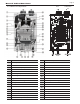
LAARS Heating Systems Page 60 Section 10 – Repair Part Diagram 10.
Mascot ST Tankless Water Heater Cover Assembly Page 61
eft), Right) 17-1 17-2 Page 17-3 62 17-4 18 19 Part 20 list 31 31-1 31-2 31-3 31-4 31-5 31-6 32 32-1 32-2 32-3 33 34 35 35-1 35-2 35-3 35-4 35-5 35-6 36 37 38 39 40 41 42 43 44 45 46 47 47-1 47-2 48 49 50 51 ST1022 ST1023 ST1024 ST1025 ST1026 ST1027 ST1028 ST1029 ST1030 ST1031 ST1032 ST1033 ST1034 ST1035 ST1036 ST1037 ST1038 ST1039 ST1040 ST1041 ST1042 ST1043 ST1044 ST1045 ST1046 ST1047 ST1048 ST1049 ST1050 ST1051 ST1052 ST1053 ST1054 ST1055 ST1056 ST1057 ST1058 FT1538 ST1060 ST1061 ST1062 FT1728 ST1064 S
870060043 11400020 160420004 49100124 11300015 160522003 5 ST1007 Gas Inlet Nipple 6 ST1008 Overheat Sensor Mascot 7 ST Tankless ST1009 Water DHW Heater Supply Pipe ASS'Y 7-1 ST1010 DHW Supply Pipe 7-2 ST1011 Water Outlet Sensor 8 ST1012 Siphon ASS'Y 9 ST1013 Siphon Air Pressure Hose 64100022 10 ST1014 Air Pressure Switch 64100022 11 ST1015 MMI Bracket 140350003 12 ST1016 MMI 14110021 13 ST1017 PCB 140210024 14 ST1018 PCB Bracket 140210024 15 ST1019 Manual Switch 64100048 16 ST1020 Flow Control Valve 16040
Page 64 Notes: LAARS Heating Systems
Mascot ST Tankless Water Heater Notes: Page 65
LAARS Heating Systems Notes: H2372600B Dimensions and specifications subject to change without notice in accordance with our policy of continuous product improvement. Customer Service and Product Support: 800.900.9276 • Fax 800.559.1583 Headquarters: 20 Industrial Way, Rochester, NH, USA 03867 • 603.335.6300 • Fax 603.335.3355 1869 Sismet Road, Mississauga, Ontario, Canada L4W 1W8 • 905.238.0100 • Fax 905.366.0130 www.Laars.com Litho in U.S.A.