
Install Instructions
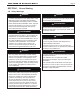
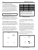
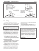
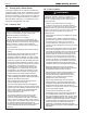
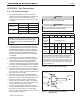
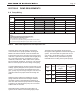
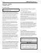
Table Of Contents
- Cover
- TABLE OF CONTENTS
- SECTION 1 GENERAL INFORMATION
- SECTION 2 LOCATING THE BOILER
- SECTION 3 AIR AND VENTING
- SECTION 4 GAS CONNECTIONS
- SECTION 5 PUMP REQUIREMENTS
- SECTION 6 WATERCONNECTIONS
- SECTION 7 ELECTRICAL AND WIRING DIAGRAMS
- SECTION 8 THE DIGITAL DASHBOARD
- SECTION 9 INITIAL STARTUP
- SECTION 10 MAINTENANCE
- SECTION 11 OPERATING DETAILS AND TROUBLESHOOTING
- SECTION 12 REPLACEMENT PARTS

Page 17
Gas Supply
Inlet
Tee
Fitting
3 in.
(76mm) Min.
Cap
Nipple
To Equipment
Inlet
Figure 8. Typical design for a sediment
trap/drip leg.
MINI-THERM JX Residential Boilers
®
2. Check the gas supply to be sure that it is the same
as the gas indicated on the boiler’s plate. This boiler,
as shipped from the factory, is certied to operate
within the altitude range indicated on the rating plate.
If a eld conversion to a dierent altitude range or
dierent gas should be necessary, conversion parts
are available.
See Section 12.C on page 50 for part numbers.
3. Use the gures in Table 4 to size the gas inlet piping
from the gas meter to the heater. Check all local
codes for compliance before installing the heater.
4. A sediment trap (drip leg) must be installed ahead
of the gas controls (see Figure 8). Fit the trap with
a threaded cap which can be removed for cleaning.
5. Install a manual gas shuto valve for service and
safety. Do not use a restrictive gas cock. Flexible
gas connectors, if used, must be CSA rated for the
total input rating of the boiler.
6. Disconnect the boiler and its individual shuto
valve from the gas supply system during pressure
testing of the system at pressures higher than 1/2
pounds per square inch (psi) (3.45 kilopascals
[kPa]). If the test pressure is equal to or less than
1/2 psi (3.45 kPa), close the manual shuto valve
on the heater during the pressure test.
7. If the gas supply pressure is less than required,
check for undersized pipe between the meter and
the boiler, a restrictive tting, or an undersized
gas meter. Gas supply pressures to the heater are
listed in Table 3 on page 17.
SECTION 4 Gas Connections
4.A Gas Supply and Piping
1. Gas piping installation must be in accordance
with the latest edition of ANSI Z223.1 and all local
codes. In Canada, the installation must be in
accordance with CSA-B149.1 and all local codes
that apply.
CAUTION
Permanent damage to the gas valve will occur if the
following procedures are not followed.
ATTENTION
Vous endommagerez la soupape de gaz si vous ne
respectez pas les procédures suivantes.
NOTE: The maximum inlet gas pressure must not
exceed the specied value. The minimum value
listed is for the purpose of input adjustment. Refer
to Table 4
Table 3. Gas Supply Pressure Requirements
Supply Pressure Minimum Maximum
Natural Gas
5.5 Inches WC 10.5 Inches WC
(1.3 kPa) (2.5 kPa)
LP Gas
10.0 Inches WC 13.0 Inches WC
(2.4 kPa) (3.1 kPa)
Table 4. Gas Pipe Size Requirements*
Boiler Size
50 75 100 125 150 200
Needed Pipe Size
0-50ft
0-15m
1/2 3/4 3/4 3/4 3/4 1
50-100ft
15-30m
1/2 3/4 3/4 1 1 1-1/4
100-200ft
30-60m
3/4 1 1 1 1-1/4 1-1/4
*Note: These gures are for Natural Gas (.65 Sp. Gr.),
and are based on 1/2" water column pressure drop.
For LP (1.5 Sp. 11” wc) and 1/2” water column drop.
Check supply pressure with a manometer, and local code
requirements for variations. Pipe ttings must be consid-
ered when determining gas pipe size. See National Fuel
Gas Code or local code requirements for complete pipe
sizing requirements.
Equivalent
Distance
From Gas
Meter
1/2”1/2”
1/2”
1/2”
1/2”
1/2” 3/4” 3/4”
3/4”3/4” 3/4”
3/4”
3/4”3/4”
3/4” 1” 1”
1”
continued on next page.