
Install Instructions
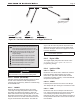
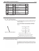
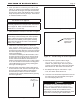
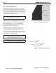

Table Of Contents
- Cover
- TABLE OF CONTENTS
- SECTION 1 GENERAL INFORMATION
- SECTION 2 LOCATING THE BOILER
- SECTION 3 AIR AND VENTING
- SECTION 4 GAS CONNECTIONS
- SECTION 5 PUMP REQUIREMENTS
- SECTION 6 WATERCONNECTIONS
- SECTION 7 ELECTRICAL AND WIRING DIAGRAMS
- SECTION 8 THE DIGITAL DASHBOARD
- SECTION 9 INITIAL STARTUP
- SECTION 10 MAINTENANCE
- SECTION 11 OPERATING DETAILS AND TROUBLESHOOTING
- SECTION 12 REPLACEMENT PARTS

Page 37
6. When pilot ame is sensed the green “ame” LED
will turn on. If ame is not sensed in 75 seconds the
pilot valve will de-energize, the spark will terminate,
and the green “ame” LED will blink. After a 5 minute
delay the sequence will retry at step 5. There will be
an unlimited number of retries.
NOTE: Check for good quality pilot ame.
See Section 9.C on page 38.
NOTE: Check the ame current and make the
necessary adjustments to the pilot valve. See Section
9.C on page 38. Flame current should be set to a
minimum of 1. O micro amp.
7. When pilot ame is sensed, the main valve is energized.
NOTE: The limits, damper switch and pilot ame are
continuously monitored during main valve operation.
If any of these are opened or pilot ame is lost the
main valve is immediately de-energized. A blinking
green LED will indicate the cause of the shutdown
(limits, v-sw, or ame).
8. Observe the main ame pattern on all burners.
There should be minimal pulsing, unstable or lifting
ame patterns. For any abnormal ame check gas
pressures and orice alignment. If the gas pressures
and orice alignments are good, then the air shutter
needs to be adjusted.
On all burners exhibiting an abnormal ame, use a
5/16 inch wrench to loosen (do not remove) the air
shutter locking screw. Slowly close or open the air
shutter until a normal ame is observed then re-
tighten its associated locking screw. Factory setting
is .75” from shutter to burner orice mounting plate.
Use the Mini-Gauge to set to factory starting point.
See Figure 29 and Figure 30.
9. After the startup, the ignition system safety device
must be tested. To test, close the manual gas valve
and verify that the burner ame is extinguished
and the boiler proceeds to a lock out condition
(continuous retry of pilot). Restart boiler by opening
the manual gas valve.
10. Allow the boiler to operate until the target
temperature or high temperature set point is
reached. The yellow “target” LED or the yellow
“hi-temp” LED will light. The main burner and pilot
ame will turn o. The “ame” LED will turn o.
11. The damper will begin to close and the “v-pwr’’,
“v-sw”, and “limits” LEDs will turn o.
12. Lower the room thermostat temperature to remove
the call for heat. The third decimal, lower right of
the control display will turn o
WARNING
Fire, explosion, or carbon monoxide hazard. Water
damage can lead to unreliable operation or cause
the control to malfunction which could lead to severe
personal injury or death. Do not install the control
module where it can get wet. Always replace the control
if it gets wet or if it has any signs of water residue.
Figure 28. The Mini-Gauge for Orice Adjustment
Mini Gage stands
vertically for
Orice Angle
Adjustment
Air shutter
locking screw
Figure 29. The Mini-Gauge for Shutter Adjustment
Figure 30. The Mini-Gauge for Orice Adjustment
MINI-THERM JX Residential Boilers
®