
Install Instructions
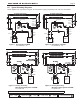
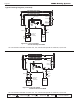
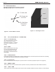
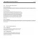
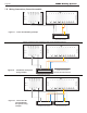
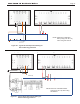

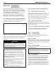
Table Of Contents
- Cover
- TABLE OF CONTENTS
- SECTION 1 GENERAL INFORMATION
- SECTION 2 LOCATING THE BOILER
- SECTION 3 AIR AND VENTING
- SECTION 4 GAS CONNECTIONS
- SECTION 5 PUMP REQUIREMENTS
- SECTION 6 WATERCONNECTIONS
- SECTION 7 ELECTRICAL AND WIRING DIAGRAMS
- SECTION 8 THE DIGITAL DASHBOARD
- SECTION 9 INITIAL STARTUP
- SECTION 10 MAINTENANCE
- SECTION 11 OPERATING DETAILS AND TROUBLESHOOTING
- SECTION 12 REPLACEMENT PARTS

Page 24
7.D Field Connections
This boiler has three Field Connection Terminals.
TB1, TB2 and TB3 (TB3 is for optional equipment).
7.D.1 TB1 (Terminal Block 1 -TT, DHW, OAS)
7.D.1.a TT (Central Heat)
TT is for the end switch of a zone
relay control system or direct
thermostat connection. It controls
the boiler to maintain the central
heating.
7.D.1.b DHW.
Either a tank aquastat or the leads
from the optional DHW Relay Kit
will control the boiler to the high
limit setpoint. See SECTION 8 for
functionality.
Figure 15. Terminal Block Locations
TB3 -DHW Relay
Connections
(optional)
TB2 -Pumps and
Aux Power
TB1 -TT, DHW, OAS
7.D.1.c Field Interlocks
Field Interlocks allow for auxiliary limits or LWCO. Breaking these connections prevents the boiler from operating.
The LIMITS LED will ash while these connections are open.
7.D.1.d PV Terminals
PV1, PV2 and PV4 (PV Terminals) are for power venters or air make up equipment (See 7.E on page 26).
7.D.1.e WWSD + COM
10K ᾨ outdoor air sensor will cause boiler to operate in economy mode but have warm weather shut down.
7.D.1.f OAS + COM
10K ᾨ outdoor air sensor provides outdoor reset control and warm weather shut down, based on control settings.
Figure 16. Unlocking the Cover
Open
Closed
LAARS Heating Systems