
Install Instructions
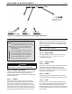
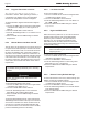
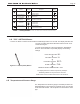
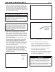
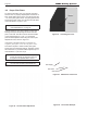
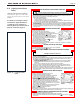

Table Of Contents
- Cover
- TABLE OF CONTENTS
- SECTION 1 GENERAL INFORMATION
- SECTION 2 LOCATING THE BOILER
- SECTION 3 AIR AND VENTING
- SECTION 4 GAS CONNECTIONS
- SECTION 5 PUMP REQUIREMENTS
- SECTION 6 WATERCONNECTIONS
- SECTION 7 ELECTRICAL AND WIRING DIAGRAMS
- SECTION 8 THE DIGITAL DASHBOARD
- SECTION 9 INITIAL STARTUP
- SECTION 10 MAINTENANCE
- SECTION 11 OPERATING DETAILS AND TROUBLESHOOTING
- SECTION 12 REPLACEMENT PARTS

Page 38
9.C Proper Pilot Flame
To view the pilot ame, the cover must be unlocked
and removed. A properly adjusted pilot should have a
blue, steady ame with an inner cone that engulfs 3/8”
- 1/2” of the pilot ignitor sensor. The pilot ignitor sensor
should glow bright orange from the heat and the ame
current should be 1.0 μA to 1.8 μA.
NOTE: To read ame current see Section "8.D TEST
/ SETTINGS Button" on page 35
If the pilot ame is over sized, orange in color, and
blowing far beyond the pilot ignitor sensor then the
pilot is over red. The ame current will read outside
of the nominal range of 1.0 μA – 1.8 μA and the
pilot should be adjusted down using the valve's pilot
adjustment screw, shown in Figure 31.
If the ame is small and the inner cone does not
engulf the pilot ignitor sensor then the pilot is under
red. When the pilot is under red the pilot ignitor
sensor does not glow bright orange. The ame current
will read below 1.0 μA and should be adjusted up to a
value between 1.0 μA and 1.8 μA.
NOTE: If the ame current reads below 0.8 μA the
control will continue to spark as it does not
recognize an acceptable ame current.
Figure 31. The Gas Valve Adjustment
Figure 32. Unlocking the Cover
Open
Closed
Gas Supply
Gas Valve
Gas Pilot
Figure 33. Without the Front Cover
Figure 34. Pilot Flame Example
NOTE: Flame Current reading will remain in the display
for 30 seconds to allow for pilot adjustment.
LAARS Heating Systems