
Install Instructions

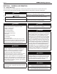
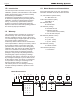
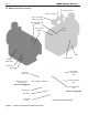
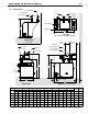
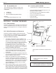
Table Of Contents
- Cover
- TABLE OF CONTENTS
- SECTION 1 GENERAL INFORMATION
- SECTION 2 LOCATING THE BOILER
- SECTION 3 AIR AND VENTING
- SECTION 4 GAS CONNECTIONS
- SECTION 5 PUMP REQUIREMENTS
- SECTION 6 WATERCONNECTIONS
- SECTION 7 ELECTRICAL AND WIRING DIAGRAMS
- SECTION 8 THE DIGITAL DASHBOARD
- SECTION 9 INITIAL STARTUP
- SECTION 10 MAINTENANCE
- SECTION 11 OPERATING DETAILS AND TROUBLESHOOTING
- SECTION 12 REPLACEMENT PARTS

Page 10
Figure 3. Minimum Clearances
SECTION 2 LOCATING THE BOILER
2.A Field Assembly
This boiler is shipped with an automatic vent damper that
must be assembled onto the vent collar on the top of the
boiler, and then plugged into the unit using the dedicated
harness.
2.B Boiler Placement and Clearances
This boiler is design certied by CSA-International for
indoor installation on combustible ooring, in basements,
in closets, utility rooms or alcoves. These units must
never be installed on carpeting.
1. This boiler is designed for indoor installations only
and should be located to provide clearances on all
sides for maintenance and inspection. See Figure
3. It should not be located in an area where leakage
of any connections will result in damage to the
area adjacent to the unit or to lower oors of the
structure. When such a location is not available, it is
recommended that a suitable drain pan, adequately
drained, be installed under the unit.
2. A minimum of 15” (381mm) access must be available
in front of the boiler for burner removal. Consult
local codes for clearances to hot water pipes and
accessories.
3. If the boiler is to be installed in a garage, all burners
and burner ignition devices must have a minimum 18”
(457mm) clearance above the oor.
4. Boilers can be installed in a closet as long as all
minimum clearances are followed, including between
the front of the boiler and the closet door when it is
closed. See Figure 3. Consult the American National
Standard Z21.13 for more information concerning
closet installations. In Canada, refer to the latest
edition of CSA-B149.1.
5. When vented vertically, the unit must be located as
close as practical to the vertical section of the vent.
When a power venter is used with a terminal through
a wall, and there is a potential for snow accumulation,
the terminal must be installed at an appropriate level
above grade or the maximum expected snow
line.
NOTE: For installation on combustible ooring.
Installer seulement sur un plancher
combustible.
NOTE: For Closet Installation Clearances, the
minimum clearance between hot water pipes
and combustible construction is 1” (2.5 cm.)
LAARS Heating Systems
4” 10 cm
4” 10 cm
6” 15 cm
20” 51 cm
2” 5 cm
1.G The Installation Kit
This residential unit is shipped in a single crate
with a boxed installation kit that contains these
components.
1. I/O Manual
2. Vent Damper
3. Burner Air Bae Gauge (Mini Gauge)
Optional:
1. Circulator pump & ange kit (50 - 100)
1.H Accessory Kits Available
See Section 12.C on page 50 for part numbers.
• Low Loss Header with Integral Pump for 50 - 100
(Standard on larger models)
• Conversion kits for LP and altitude are available
from 0 to 10,000’ both fuels.
• Domestic Hot Water Pump Relay Kit
• Power Vent Kits
• Outdoor Air Sensor