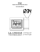
WT-5110 433 MHz Radio Controlled Projection Alarm Instruction Manual
TABLE OF CONTENTS Topic Inventory of Contents/ Additional Equipment About WWVB Quick Set-Up Guide Page 3 3 4 Detailed Set-Up Guide Battery Installation Program Mode Programming Sequence Function Buttons Manual Time Setting Time Zone Setting Daylight Saving Time (DST) Setting 6 6 6 6-7 7 Features & Operations Features Radio-Controlled Time Projection LED Backlight Indoor Temperature Indoor Humidity Time Alarm Changing Display Mode Maintenance & Care Troubleshooting Specifications Warranty and Contact Inf
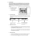
INVENTORY OF CONTENTS 1) WT-5110 Alarm Clock 2) AC adapter/transformer 3) Instruction manual and warranty card. ADDITIONAL EQUIPMENT (not included) 1) Two fresh 1.5V AA batteries (optional for projection alarm clock) FEATURES OF PROJECTION ALARM Operation of these features is in section III 1. 2. 3. 4. 5.
QUICK SET-UP GUIDE Hint: Use good quality Alkaline Batteries and avoid rechargeable batteries. 1. We recommend beginning the set-up procedure at night when the WWVB signal is easiest to receive. 2. It is also highly recommended to set the projection alarm in a window or other area free of interference in the area of your home that is closest to Colorado (the source of the WWVB signal). NOTE: The above steps are not required but can help the projection alarm receive the signal faster. 3.
DETAILED SET-UP GUIDE I. BATTERY INSTALLATION A. PROJECTION ALARM 1. 2. 3. 4. 5. Remove the battery cover. Observe the correct polarity, and install 2 AA batteries. In addition or instead of inserting batteries, the AC adapter can be used. Simply plug the adapter into the receptacle on the underneath of the alarm clock and then plug in adapter. Replace the battery cover. The projector will activate and remain on if the alarm clock is plugged in.
II. PROGRAM MODE To enter the Program Mode hold down the “MODE/MIN” button for 3 seconds, until the time flashes in the top of the display. The Program Mode Guide is laid out in a manner that allows you to program each function separately, or you can follow the instructions entirely to program the projection alarm. Complete programming is usually done for the initial set-up, and will require you to skip step 1 and 2 of programming sections D and E.
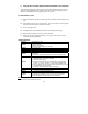
4. Press and release the “MODE/MIN” button to select the appropriate time zone. There are 24 time zones to choose from (based relative to the international time standard of GMT (“Greenwich Mean Time). NOTE: The U.S. time zones will show abbreviations as opposed to the numerical time zone indicator. For example Eastern Time will display “ET” when the Eastern Time Zone is selected 5.
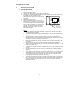
III. FEATURES & OPERATIONS A. FEATURES 1. 2. 3. 4. 5. Radio-controlled time Projection of time LED backlight Display of indoor temperature/humidity or alarm time Time alarm B. RADIO-CONTROLLED TIME 1. The projection alarm will automatically search for the time signal upon initial set-up and every night. 2. When the signal is being received, there will be a “tower” icon flashing to the left of the time display. 3.
D. LED BACKLIGHT 1. 2. E. INDOOR TEMPERATURE 1. 2. 3. 4. F. The projection alarm measures indoor temperature with an internal sensor. This temperature is displayed in °F. The indoor temperature will take time to adjust to the surrounding temperature as the sensor is inside the case. If the remote temperature is placed next to the projection alarm, more often than not the temperature will not be exact with one another. This is not a defect, but simply reflects the difference in measuring methods.
H. CHANGING DISPLAY MODE (INDOOR TEMPERATURE/HUMIDITY OR ALARM TIME) There are two possible display modes in the indoor temperature/humidity section of the LCD (lower left); indoor temperature and humidity or alarm time. To change the display press and release the “MODE/MIN” button to toggle between the two modes. IV. MAINTENANCE & CARE A. Extreme temperatures, vibrations, and shock should be avoided to prevent damage to the units. B. Clean displays and units with a soft, damp cloth.
SPECIFICATIONS FOR WT-5110 Temperature: Measuring range: 14°F to 99°F with 0.2°F resolution Checking intervals: Every 10 seconds Humidity Measuring range: 1 – 99% Checking intervals: Every 10 seconds Power source: AC Adapter (included) Input: 120VAC/60Hz Output: DC 6V/100MA Battery type: 2 x AA, 1.5V (Alkaline recommended) (optional) Battery life: Approximately 12 months, depending on projection and backlight use Dimensions (H x W x D): Projection Alarm Clock 3.5 x 5.5 x 2 in (90.6 x 140.
WARRANTY INFORMATION La Crosse Technology, Ltd provides a 1-year limited warranty on this product against manufacturing defects in materials and workmanship. This limited warranty begins on the original date of purchase, is valid only on products purchased and used in North America and only to the original purchaser of this product. To receive warranty service, the purchaser must contact La Crosse Technology, Ltd for problem determination and service procedures.
For warranty work, technical support, or information contact: La Crosse Technology, Ltd 2809 Losey Blvd. S. La Crosse, WI 54601 Phone: 608.782.1610 Fax: 608.796.1020 e-mail: support@lacrossetechnology.com (warranty work) sales@lacrossetechnology.com (information on other products) web: www.lacrossetechnology.com FCC DISCLAIMER This device complies with part 15 of the FCC rules.
WS-9117U Wireless 433 MHz Temperature Station Instruction Manual 1
TABLE OF CONTENTS Topic Inventory of Contents Quick Setup Detailed Setup Guide Battery Installation Setting the Time Selecting Units of Measurement Features Minimum and Maximum Temperatures Resetting Minimum and Maximum Temperatures Additional remote temperature sensors (optional) Mounting Troubleshooting Maintenance and Care Specifications Warranty Information Page 3 4-8 9-11 11-12 12-13 13 13-14 14-16 17-18 19-20 21 22-23 24-28 2
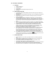
INVENTORY OF CONTENTS 1. The indoor temperature station (Figure 1) 2. The remote temperature sensor (TX6U) and mounting bracket. (Figure 2) 3. 3 each, 1/2” Philips screws. 4. One strip of double sided adhesive tape. 5. Instruction Manual and Warranty Card. Figure 2 Figure 1 ADDITIONAL EQUIPMENT (not included) 1. 1 Philips screwdriver. 2. 2 Fresh AAA 1.5V batteries. 3. 2 Fresh AA 1.5V batteries.
QUICK SETUP Hint: Use good quality Alkaline Batteries and avoid rechargeable batteries. 1. Have the indoor temperature station and remote temperature sensor 3 to 5 feet apart. 2. Batteries should be out of both units for 10 minutes. 3. Place the batteries into the remote temperature sensor first then into the indoor temperature station. (All remote temperature sensors must be started before the indoor temperature station) 4. DO NOT PRESS ANY BUTTONS FOR 15 MINUTES.
In this time the indoor temperature station and remote temperature sensor will start to talk to each other and the display will show both the indoor temperature and an outdoor temperature. If the indoor temperature station does not display both temperatures after the 10 minutes please retry the set up as stated above. After both indoor and outdoor temperatures are displayed for 15 minutes you can place your remote temperature sensor outdoors and set your time.
of resistance. Your distance plus resistance should not exceed 80 ft. in a straight line. NOTE: Fog and mist will not harm your remote temperature sensor but direct rain must be avoided. To complete the set up of your indoor temperature station after the 15 minutes have passed please follow the steps below. 1. Press and hold the “SET/CH” button for 5 seconds. Note: A “12h” or “24h” will appear to the left of the time. (“12h” for AM/PM, “24h” for military time) a.
b. 2. 3. When you have your choice shown on the display press and release the “SET/CH” button once. Degree Fahrenheit will now show. a. To change between Fahrenheit and Celsius, press and release the “MIN/MAX” button. b. When you have your choice shown on the display press and release the “SET/CH” button once. An hour will now be flashing. a. Press and release the “MIN/MAX” button until the correct hour is shown.
the word TIME when in the PM hours. During the AM hours this area will be blank. b. When the correct hour is shown, press and release the “SET/CH” button once. 4. A minute will now be flashing. a. Press and release the “MIN/MAX” button until the correct minutes are displayed. Press and release the “SET/CH” button once more and you are done.
DETAILED SETUP GUIDE I. BATTERY INSTALLATION A. REMOTE TEMPERATURE SENSOR 1. Remove the mounting bracket. 2. Remove battery cover 3. Observing the correct polarity, install 2 AA batteries—make sure they do not spring free, or start-up problems may occur. Replace cover.
B. INDOOR TEMPERATURE STATION Note: After the batteries are installed, DO NOT press any buttons. This may interfere with the signals, causing temperatures to register incorrectly. 1. Remove the battery cover on the backside. 2. Observing the correct polarity, install 2 AAA batteries. 3. Replace battery cover. 4. Wait 15 minutes before pressing any buttons.
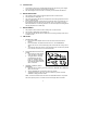
5. The indoor temperature station should now show: “-:- -” in the TIME LCD, and temperatures in the INDOOR and OUTDOOR LCD’s. II. TIME A. SETTING THE TIME 1. Press and hold the “SET/CH” button for 5 second, “12h” will appear in the TIME LCD. 2. Press and release the “MIN/MAX” button to select either 12h time (am/pm) or 24h time 3. Press and release the “SET/CH” button 2 times, the hour will flash in the upper left corner. 4.
5. Press and release the “SET/CH” button to move to the minute setting 6. Press and release the “MIN/MAX” button to set the minutes. 7. Press and release the “SET/CH” button to activate the clock. Note: When in 12h mode, there is only a “PM” display, which appears under “TIME.” If there is no display here it is AM. Make sure you set the time accordingly. III. UNITS OF TEMPERATURE MEASURE A. SELECTING UNITS OF MEASUREMENT 1.
3. Press and release the “MIN/MAX” button to shift between °F and °C. 4. Press and release the “SET/CH” button twice to activate settings. IV. FEATURES A. MINIMUM AND MAXIMUM TEMPERATURES 1. Press and release the “MIN/MAX” button, “MIN” appears in the temperature LCD’s and the recorded minimum temperatures are displayed. 2. Press and release the “MIN/MAX” button to toggle to the maximum temperatures. The time of occurrence of the value for outdoor temperature will also flash. B.
seconds. C. ADDING ADDITIONAL REMOTE TEMPERATURE SENSORS (OPTIONAL) 1. The WS-9117U is able to receive signals from 3 different remote temperature sensors. Following are some brief instructions for the basic set-up of remote temperature sensor units with the WS-9117U. These extra sensors can be purchased through the same dealer as this unit, or by contacting La Crosse Technology directly.
remote temperature sensor units, and in numeric sequence. Second, install batteries into the indoor temperature station. Transmission problems will arise if this is not done correctly and if the total time for set-up exceeds 6 minutes. 2. It is necessary to remove the batteries from all units currently in operation. 3. Remove the battery covers to all remote temperature sensor units. 4. Place all remote temperature sensor units in a numeric sequential order. 5.
D. VIEWING AND OPERATING WITH MULTIPLE REMOTE TEMPERATURE SENSOR UNITS 1. To view the temperature of a different remote temperature sensor unit, press and release the “SET/CH” button. A shift from one “boxed” number to the next should be observed in the OUTDOOR LCD. 2. To view the Minimum/Maximum temperature: first select from which remote temperature sensor to read data (indicated by the “boxed” number).
V. MOUNTING Note: To achieve a true temperature reading, avoid mounting in direct sunlight. We recommend that you mount the remote temperature sensor on an outside Northfacing wall. The sending range is 80ft; obstacles such as walls, concrete, and large metal objects will reduce the range. Place both units in their desired location before permanently mounting. A. REMOTE TEMPERATURE SENSOR 1. Remove the mounting bracket from the remote temperature sensor 2. Mount using either screws or adhesive tape. 3.
that is required is to place the indoor temperature station in an appropriate location. 2. To wall mount, remove the table stand. To do this, pull down on the stand from the rear and rotate forward. a) Fix a screw (not included) into the desired wall, and place the indoor temperature station onto the screw using the hanging hole on the backside. Gently pull the indoor temperature station down to lock the screw into place.
TROUBLESHOOTING NOTE: For problems not solved, please contact La Crosse Technology via e-mail or phone, or visit our website, www.lacrossetechnology.com Problem: The LCD is faint Solution: Replace batteries Problem: No outdoor temperature is displayed. Solution: 1) Remove all batteries, reinsert into remote temperature sensor first, and then into the indoor temperature station. 2) Place remote temperature sensor closer to the indoor temperature station. 3) Be sure all batteries are fresh.
Problem: Temperatures do not match if units are placed next to each other. Solution: Each temperature sensor is manufactured to be accurate to within 1 degree plus or minus and under normal conditions; so two temperature sensors could be as much as 2 degrees different. However, the difference can be exaggerated further because the temperature sensors are designed for different working environments.
MAINTENANCE AND CARE INSTRUCTIONS • • • • • Extreme temperatures, vibration, and shock should be avoided to prevent damage to the units. Clean displays and units with a soft, damp cloth. Do not use solvents or scouring agents; they may mark the displays and casings. Do not submerge in water. Do not subject the units to unnecessary heat or cold by placing them in the oven or freezer. Opening the casings invalidates the warranty. Do not try to repair the unit. Contact La Crosse Technology for repairs.
SPECIFICATIONS Transmitting 433MHz Frequency Measuring Temperatures Indoor 32°F to 140°F with 0.2°F Temperature resolution. Station: Indoor (0°C to 69.0°C with 0.1°C resolution) Indoor -21.8 °F to 156.2°F with Temperature 0.2°F resolution. Station: Outdoor (-29.9°C to 69.0°C with 0.1°C resolution) Temp accuracy +/- 1°F (+/- .5°C) Transmitting Maximum 80 feet (25m) range open space Temperature check Indoor Every 10 seconds Outdoor Two times in 10 minutes Batteries—(Alkaline recommended) 2 x AA, 1.
Temperature Station Dimensions: (H x W x D) 5 x 2.25 x 1 in Indoor (excluding table stand) Temperature (125 x 58 x 23 mm) Station Remote 5 x 1.5 x 1 in Temperature (128 x 40 x 23 mm) Sensor Battery life Approximately 1 year WARRANTY INFORMATION La Crosse Technology, Ltd provides a 1-year limited warranty on this product against manufacturing defects in materials and workmanship.
purchase to La Crosse Technology, Ltd or La Crosse Technology, Ltd’s authorized service center. La Crosse Technology, Ltd will repair or replace this product, at our option and at no charge as stipulated herein, with new or reconditioned parts or products if found to be defective during the limited warranty period specified above. All replaced parts and products become the property of La Crosse Technology, Ltd and must be returned to La Crosse Technology, Ltd.
be presented to the carrier); (3) damage to, or deterioration of, any accessory or decorative surface; (4) damage resulting from failure to follow instructions contained in your owner’s manual; (5) damage resulting from the performance of repairs or alterations by someone other than an authorized La Crosse Technology, Ltd authorized service center; (6) units used for other than home use (7) applications and uses that this product was not intended or (8) the products inability to receive a signal due to any
consequential or incidental damages therefore the above exclusion of limitation may not apply to you. For warranty work, technical support, or information contact: La Crosse Technology 2809 Losey Blvd. S. La Crosse, WI 54601 Phone: 608.782.1610 Fax: 608.796.1020 e-mail: support@lacrossetechnology.com (warranty work) sales@lacrossetechnology.com (information on other products) web: www.lacrossetechnology.com FCC DISCLAIMER This device complies with part 15 of the FCC rules.
Freq. 433.92 MHz La Crosse Technology Made in China WS-9117U FCC ID: OMO-01RX (Receiver), OMO-01TX (sensor) THIS DEVICE COMPLIES WITH PART 15 OF THE FCC RULES. OPERATION IS SUBJECT TO THE FOLLOWING TWO CONDITIONS: 1. THIS DEVICE MAY NOT CAUSE HARMFUL INTERFERENCE, AND 2. THIS DEVICE MUST ACCEPT INTERFERENCE RECEIVED, INCLUDING INTERFERENCE THAT MAY CAUSE UNDESIRED OPERATION.