
Installation & User Guide
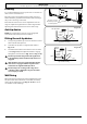
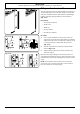

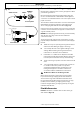
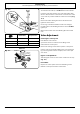
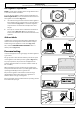

Table Of Contents
- 1. Important safety information
- 2. Range overview
- 3. Cooking tips
- 4. Cooking table
- 5. Cleaning your range
- 6. Troubleshooting
- 7. Installation Instructions
- 8. Service and parts
- 9. Installation safety instructions
- 10. Installation
- 11. Gas connection
- 12. Conversion to LP Gas
- 13. Electrical connection
- 14. Final fitting and checks
- 15. Circuit diagram
- 16. Technical data
- 17. Warranty

INSTALLATION
Check the appliance is electrically safe and gas sound when you have nished.
27
Leveling
It is recommended that you use a spirit level on a shelf in one
of the ovens to check the level.
Place the range in its intended position, taking care not to
twist it within the gap between the kitchen units as damage
may occur to the range or the units.
The front feet and rear rollers can be adjusted to level the
range. To adjust the height of the rear of the range turn the
adjusting nuts at the front bottom corners of the range.
Anti-tip device
NOTE: The range must be set to the correct height and
leveled before the anti-tip bracket is installed.
Fitting the anti-tip device
1. A range using a exible gas connector must be secured
with a suitable anti-tip device.
2. A suitable anti-tip device is supplied and shown in
Fig. 10.10.
3. First attach the bracket location device to the rear of the
cooker (Fig. 10.10). Then adjust the bracket to engage
through the slot of the device (Fig. 10.11 and Fig. 10.12).
DO NOT operate the range before the appliance is
in its installed position and the anti-tip devices are
engaged.
If the appliance is moved, ensure that the anti-tip
devices are re-engaged and the range has been
returned to its original installed position.
DO NOT step, lean or swing on the range doors
or drawer as this could tip the range and result in
serious injury or death.
Wall fixing
Where oor xing is impractical and provided that the outer
anti-tip bracket can be attached to a solid wall, the anti-tip
device may be attached to a wall (Fig. 10.12). Make sure to
use suitable screws and xings.
Fig. 10.10
ArtNo.070-0014 - Stability bracket - Wall fitting
Cooker
Stability
bracket
Floor
Stability
location
bracket
Wall
Typical wall mounting
ArtNo.070-0014 - Stability bracket - Wall fitting
Cooker
Stability bracket
Floor
Stability
location
bracket
Typical oor mounting
Alternative positions
for stability location
bracket
Fig. 10.11
Fig. 10.12
Alternative positions
for anti-tip device
Anti-tip bracket
Anti-tip
bracket
Anti-tip
location
bracket
Range
Range