
installation user_guide


INSTALLATION
Check the appliance is electrically safe and gas sound when you have nished.
28
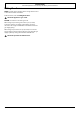
Cooker
Outer stability
bracket
Floor
Wall
3 mm min
Typical wall mounting
Outer anti-tip
bracket
Range
1/8” (3mm) min
Fig. 10.12
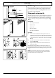
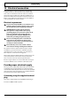
ArtNo.280-0070 - Side extension A
ArtNo.280-0071 - Side extension B
ArtNo.281-0004 - 90SC
- Fitting the side panel
ArtNo.281-0005 - Albertine SC
- Side panel in place
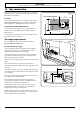
Wall fixing
Where oor xing is impractical and provided that the outer
anti-tip bracket can be attached to a solid wall, the anti-tip
device may be attached to a wall (Fig. 10.12). Make sure to
use suitable screws and xings.
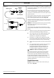
Side panel extension kit
Two side extension panels are supplied with the range. These
can be installed where the side of the range is exposed. The
extension installation must be performed by a qualied gas
installer, preferably during installation of the appliance (Fig.
10.13).
Kit Contents:
• 2x Side panel extension
• 4x M5 screw
• 4x M5 nut
• 4x Large washer
• 4x Shake-proof washer
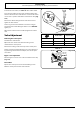
Procedure
1. Place a screw and washer in the top hole in the rear
edge of the range side panel. Add a shake-proof washer
and start the nut on the screw threads so that the screw
is loosely held in place. Repeat with the other hole (Fig.
10.14).
2. Slide the side extension in from the side behind the
washers (Fig. 10.15).
3. Tighten the top and bottom screws to hold the side
extension in place.
Reposition the range making sure the anti-tip device is re-
engaged properly when the range is replaced. Failure to take
this precaution could result in tipping of the range and cause
injury.
NOTE: Check that the extension panel does not foul the
mains lead or gas connection when the cooker is pushed
back. Reconnect the electricity supply.
Fig. 10.13
Fig. 10.14
Fig. 10.15