
installation user_guide


INSTALLATION
Check the appliance is electrically safe and gas sound when you have nished.
27
ArtNo.280-0029 - Flue Grill
ArtNo.280-0030 - Fixing Flue Grill
ArtNo.280-0031 - Flue Extension Fixing
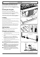
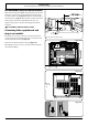
Installing the cooling fan cover
When cooking, the cooling fan cover encourages the
heat and moisture to travel up through the ue grille. This
prevents damage to your rear wall and MUST be tted (Fig.
10.6).
Installing the flue grille
The ue grille is packed separately (Fig. 10.7).
The larger of the holes along the sides are for screwdriver
access and should face to the rear. Use the screws and nuts
supplied to hold the grille in place (Fig. 10.8).
Clip the exible extensions of the oven ues to the ue grille
using the clips provided inside the ue grille (Fig. 10.9).
Leveling
It is recommended that you use a spirit level on a shelf in one
of the ovens to check the level.
Place the range in its intended position, taking care not to
twist it within the gap between the kitchen units as damage
may occur to the range or the units.
The front feet and rear rollers can be adjusted to level the
range. To adjust the height of the rear of the range turn the
adjusting nuts at the front bottom corners of the range.
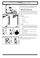
Anti-tip device
NOTE: The range must be set to the correct height and
leveled before the anti-tip bracket is installed.
Fitting the anti-tip device
1. A range using a exible gas connector must be secured
with a suitable anti-tip device.
2. A suitable anti-tip device is supplied and shown in Fig.
10.10.
3. When tting the anti-tip bracket (Fig. 10.10 and
Fig. 10.11), adjust the bracket to give the smallest
practicable clearance between the bracket and the
engagement slot in the rear of the range.
4. Fit the bracket so that it engages as far as possible over
the chassis of the range.
n
DO NOT operate the range before the appliance is
in its installed position and the anti-tip devices are
engaged.
n
If the appliance is moved, ensure that the anti-tip
devices are re-engaged and the range has been
returned to its original installed position.
n
DO NOT step, lean or swing on the range doors
or drawer as this could tip the range and result in
serious injury or death.
Fig. 10.6
Alternative positions
for anti-tip device
ArtNo.070-0014 - Stability bracket - Wall fitting
Cooker
Stability bracket
Floor
3 mm min
Typical oor mounting
0
1
⁄
8
" (3 mm) min
Range
Floor
Typical oor mounting
Anti-Tip bracket
Alternative positions for
anti-tip device
Viewed from the back
Fig. 10.7
Fig. 10.8 Fig. 10.9
Fig. 10.10
Fig. 10.11