
User Manual
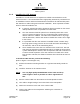
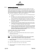
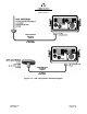
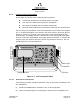
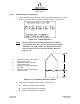
Table Of Contents
- ProTec AIS Hardware Install & Operation Manual
- Table of Contents
- List of Appendixes
- List of Figures
- Figure 1–1. AIS Transponder
- Figure 2–1. AIS Transponder
- Figure 2–2. NAV Display Screen
- Figure 2–3. Own Ship Data Display
- Figure 2–4. AIS Main System Menu
- Figure 2–5. Password Entry Screen
- Figure 2–6. System Information and Configuration Screen
- Figure 2–7. Vessel Data Setup
- Figure 2–8. Channel Management Settings Screen
- Figure 2–9. Antenna Position Screen
- Figure 2–10. Antenna Position Measurements
- Figure 2–11. Safety Text Message
- Figure 2–12. Safety Text Review Screen
- Figure 2–13. Password Change Screen
- Figure 2–14. System Alert Screen
- Figure 2–15. Alarm Status Screen
- Figure 2–16. General Status Screen
- Figure 2–17. Down-Time Log Screen
- Figure 2–18. LCD Viewing Angle Adjust Screen
- Figure 2–19. Baud Rate Setup Screen
- Figure 2–20. AIS Channel Setup Screen
- Figure 3–1. AIS Transponder Interconnection Diagram
- Figure 3–2. IEC Data Cable External Wiring Diagram
- Figure 3–3. AIS Transponder Power Cable
- Figure 3–4. Pilot Port Cable
- Figure 3–5. AIS Transponder Antenna Diagram
- Figure 3–6. AIS Transponder Rear View
- Figure 3–7. AIS Transponder MKD
- Figure 3–8. UAIS Main System Menu
- Figure 3–9. Vessel/Voyage Setup
- Figure 3–10. Antenna Position
- Figure 3–11. Calculating Antenna Position
- Figure 4–1. AIS Transponder O&D Drawing with Trunion Bracket
- Figure 4–2. AIS Transponder O&D Drawing
- Figure 4–3. IEC Data Cable Interconnect Diagram
- List of Tables
- Table 1–1. AIS Parts List
- Table 1–2. Pilot System High-Speed Input Data Formats
- Table 1–3. Pilot System High-Speed Output Data Formats
- Table 1–4. Pilot Port Pinout
- Table 1–5. Long Range Input Data and Formats
- Table 1–6. Long Range Output Data and Formats
- Table 1–7. Sensor Input Data and Formats
- Table 2–1. ProTec AIS Default Passwords
- Table 2–2. Password Type Menu Screen Access
- Table 2–3. Vessel Type Codes
- Table 2–4. Integrity Alarm Conditions Signalled Using ALR Sentence Formatter
- Table 2–5. Sensor Status Indications Signalled Using TXT Sentence Formatter
- Table 3–1. Data Channels
- Table 3–2. IEC Cable and Junction Box Pinouts
- Table 3–3. Pilot Port Pinout
- Table 3–4. ProTec AIS Default Passwords
- Table 3–5. Vessel Type Codes
- Introduction
- General
- Technical Specifications
- AIS Description
- Interface Description
- Data Field Assignments
- GPS and Sensor Input Sentences
- DTM - Datum Reference
- GBS - GNSS Satellite Fault Detection
- GGA - Global Positioning System Fix Data
- GLL - Geographic Position - Latitude / Longitude
- GNS - GNSS Fix Data
- HDT - Heading True
- RMC - Recommended Minimum Specific GNSS Data
- ROT - Rate of Turn
- VBW - Dual Ground / Water Speed
- VTG - Course Over Ground and Ground Speed
- ZDA - Time and Date
- AIS Specific Input Sentences
- GPS and Sensor Input Sentences
- Operation
- Operation
- Minimum Keyboard Display
- Keypad Description
- Data Display Screens
- Data Entry Screens
- AIS Main System Menu
- Logon / Logoff Screen
- System Information and Configuration
- Vessel/Voyage Setup
- Channel Management
- Antenna Position
- Text Messaging
- View Safety Text Log
- Change Password
- System Alert Screen
- Alarm Status
- General Status Screen
- Down-Time Log
- LCD Viewing Angle Adjustment
- Baud Rate Setup
- Set AIS Channels
- Operation
- Installation
- Drawings
- Installation Checklist

Marine Systems
Aviation Recorders
Page 3–17
Initial Issue165M0601-00
Feb. 01/05
3.1.5. PowerUp and Configuration
At this stage you should have the following steps completed:
F Transponder installed and 10–28 Vdc power connected.
F VHF antenna installed and connected to transponder.
F GPS antenna installed and connected to transponder.
F IEC data cable installed and connected to transponder and terminal block.
The next step in the installation of the AIS transponder involves setup and configura-
tion. A complete description of the interface and menu system is previously given in
Section 2. Figure 3–7 presents a view of the layout of the integral Minimum Key-
board Display. This display includes a backlit LCD screen and keypad which allows
the user to enter the required static and voyage related vessel data. A complete de-
scription of the user interface and menu system is presented in Section 2. The con-
figuration process is summarized below.
communications
Power/Dim
Status Light
Pilot Port
Display Window
STATUS
ON / OFF / DIM
Figure 3–7. AIS Transponder MKD
3.1.5.1 PowerUp the Transponder
The following procedure should be followed to carry out final setup and testing of the
AIS Transponder.
(1) Rotate the POWER button clockwise to turn on the transponder.
(2) Check the STATUS light for a steady light to ensure power is supplied to unit.