
User Manual
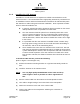
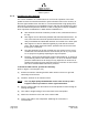
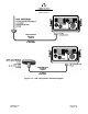
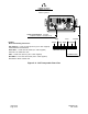
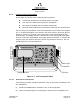
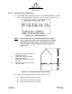
Table Of Contents
- ProTec AIS Hardware Install & Operation Manual
- Table of Contents
- List of Appendixes
- List of Figures
- Figure 1–1. AIS Transponder
- Figure 2–1. AIS Transponder
- Figure 2–2. NAV Display Screen
- Figure 2–3. Own Ship Data Display
- Figure 2–4. AIS Main System Menu
- Figure 2–5. Password Entry Screen
- Figure 2–6. System Information and Configuration Screen
- Figure 2–7. Vessel Data Setup
- Figure 2–8. Channel Management Settings Screen
- Figure 2–9. Antenna Position Screen
- Figure 2–10. Antenna Position Measurements
- Figure 2–11. Safety Text Message
- Figure 2–12. Safety Text Review Screen
- Figure 2–13. Password Change Screen
- Figure 2–14. System Alert Screen
- Figure 2–15. Alarm Status Screen
- Figure 2–16. General Status Screen
- Figure 2–17. Down-Time Log Screen
- Figure 2–18. LCD Viewing Angle Adjust Screen
- Figure 2–19. Baud Rate Setup Screen
- Figure 2–20. AIS Channel Setup Screen
- Figure 3–1. AIS Transponder Interconnection Diagram
- Figure 3–2. IEC Data Cable External Wiring Diagram
- Figure 3–3. AIS Transponder Power Cable
- Figure 3–4. Pilot Port Cable
- Figure 3–5. AIS Transponder Antenna Diagram
- Figure 3–6. AIS Transponder Rear View
- Figure 3–7. AIS Transponder MKD
- Figure 3–8. UAIS Main System Menu
- Figure 3–9. Vessel/Voyage Setup
- Figure 3–10. Antenna Position
- Figure 3–11. Calculating Antenna Position
- Figure 4–1. AIS Transponder O&D Drawing with Trunion Bracket
- Figure 4–2. AIS Transponder O&D Drawing
- Figure 4–3. IEC Data Cable Interconnect Diagram
- List of Tables
- Table 1–1. AIS Parts List
- Table 1–2. Pilot System High-Speed Input Data Formats
- Table 1–3. Pilot System High-Speed Output Data Formats
- Table 1–4. Pilot Port Pinout
- Table 1–5. Long Range Input Data and Formats
- Table 1–6. Long Range Output Data and Formats
- Table 1–7. Sensor Input Data and Formats
- Table 2–1. ProTec AIS Default Passwords
- Table 2–2. Password Type Menu Screen Access
- Table 2–3. Vessel Type Codes
- Table 2–4. Integrity Alarm Conditions Signalled Using ALR Sentence Formatter
- Table 2–5. Sensor Status Indications Signalled Using TXT Sentence Formatter
- Table 3–1. Data Channels
- Table 3–2. IEC Cable and Junction Box Pinouts
- Table 3–3. Pilot Port Pinout
- Table 3–4. ProTec AIS Default Passwords
- Table 3–5. Vessel Type Codes
- Introduction
- General
- Technical Specifications
- AIS Description
- Interface Description
- Data Field Assignments
- GPS and Sensor Input Sentences
- DTM - Datum Reference
- GBS - GNSS Satellite Fault Detection
- GGA - Global Positioning System Fix Data
- GLL - Geographic Position - Latitude / Longitude
- GNS - GNSS Fix Data
- HDT - Heading True
- RMC - Recommended Minimum Specific GNSS Data
- ROT - Rate of Turn
- VBW - Dual Ground / Water Speed
- VTG - Course Over Ground and Ground Speed
- ZDA - Time and Date
- AIS Specific Input Sentences
- GPS and Sensor Input Sentences
- Operation
- Operation
- Minimum Keyboard Display
- Keypad Description
- Data Display Screens
- Data Entry Screens
- AIS Main System Menu
- Logon / Logoff Screen
- System Information and Configuration
- Vessel/Voyage Setup
- Channel Management
- Antenna Position
- Text Messaging
- View Safety Text Log
- Change Password
- System Alert Screen
- Alarm Status
- General Status Screen
- Down-Time Log
- LCD Viewing Angle Adjustment
- Baud Rate Setup
- Set AIS Channels
- Operation
- Installation
- Drawings
- Installation Checklist

Marine Systems
Aviation Recorders
Page 3–14
Initial Issue 165M0601-00
Feb. 01/05
3.1.4. Installing the GPS Antenna
The correct installation of a GPS antenna is crucial to the operation of the trans-
ponder because the internal transmission synchronization relies on the accuracy of
the time signal obtained from the GPS. It is recommended that a high quality GPS
antenna be purchased from an established source and that all manufactures instruc-
tions be followed with particular attention to cable routing and connector installation.
Some important considerations in GPS antenna installation are:
F GPS antennas should be located to provide a clear, unobstructed view of
the sky.
F GPS signals can be affected by RADAR and SATCOM transmissions. As
such, GPS antennas should be positioned below and at least 5 meters
away from RADAR and SATCOM antennas and outside of the beam path.
F GPS signals can also be affected negatively by VHF and HF transmis-
sions, and the GPS antenna should be positioned at least 3 meters from
these types of antennas.
F The GPS antennas can be flat mounted onto any surface but it is recom-
mended that it be elevated from the deck surface (20–30 cm.) to prevent
ice or spray from negatively impacting the signal reception.
F Recently, it has been identified that certain makes/models of TV antennas
can drastically interfere with GPS reception. As such, the installer should
place the GPS antenna as far away from any shipboard TV antennas as
possible and confirm that any antennas used on board are not ones which
have been exhibited GPS interference problems.
To install the GPS antenna, perform the following:
(Refer to Figure 3–5 and Figure 3–6.)
(1) Position the antenna mounting bracket and/or antenna mast on a rigid and
structurally sound surface.
(2) Install the antenna on the antenna mount.
NOTE: Use only high quality RG213/RG214 coaxial cable and keep cable
length as short as possible to reduce signal attenuation.
(3) Run the coaxial cable from the antenna to the transponder location through an
existing throughhull.
(4) Trim cable to length leaving a few inches slack at the transponder.
(5) Attach the connectors to the end of the coaxial cable.
(6) Connect the cable to the transponder. Soldering the connection is
recommended.