
User Manual
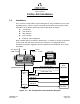
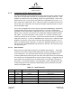
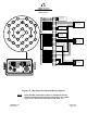
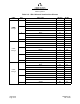
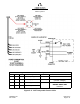
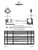
Table Of Contents
- ProTec AIS Hardware Install & Operation Manual
- Table of Contents
- List of Appendixes
- List of Figures
- Figure 1–1. AIS Transponder
- Figure 2–1. AIS Transponder
- Figure 2–2. NAV Display Screen
- Figure 2–3. Own Ship Data Display
- Figure 2–4. AIS Main System Menu
- Figure 2–5. Password Entry Screen
- Figure 2–6. System Information and Configuration Screen
- Figure 2–7. Vessel Data Setup
- Figure 2–8. Channel Management Settings Screen
- Figure 2–9. Antenna Position Screen
- Figure 2–10. Antenna Position Measurements
- Figure 2–11. Safety Text Message
- Figure 2–12. Safety Text Review Screen
- Figure 2–13. Password Change Screen
- Figure 2–14. System Alert Screen
- Figure 2–15. Alarm Status Screen
- Figure 2–16. General Status Screen
- Figure 2–17. Down-Time Log Screen
- Figure 2–18. LCD Viewing Angle Adjust Screen
- Figure 2–19. Baud Rate Setup Screen
- Figure 2–20. AIS Channel Setup Screen
- Figure 3–1. AIS Transponder Interconnection Diagram
- Figure 3–2. IEC Data Cable External Wiring Diagram
- Figure 3–3. AIS Transponder Power Cable
- Figure 3–4. Pilot Port Cable
- Figure 3–5. AIS Transponder Antenna Diagram
- Figure 3–6. AIS Transponder Rear View
- Figure 3–7. AIS Transponder MKD
- Figure 3–8. UAIS Main System Menu
- Figure 3–9. Vessel/Voyage Setup
- Figure 3–10. Antenna Position
- Figure 3–11. Calculating Antenna Position
- Figure 4–1. AIS Transponder O&D Drawing with Trunion Bracket
- Figure 4–2. AIS Transponder O&D Drawing
- Figure 4–3. IEC Data Cable Interconnect Diagram
- List of Tables
- Table 1–1. AIS Parts List
- Table 1–2. Pilot System High-Speed Input Data Formats
- Table 1–3. Pilot System High-Speed Output Data Formats
- Table 1–4. Pilot Port Pinout
- Table 1–5. Long Range Input Data and Formats
- Table 1–6. Long Range Output Data and Formats
- Table 1–7. Sensor Input Data and Formats
- Table 2–1. ProTec AIS Default Passwords
- Table 2–2. Password Type Menu Screen Access
- Table 2–3. Vessel Type Codes
- Table 2–4. Integrity Alarm Conditions Signalled Using ALR Sentence Formatter
- Table 2–5. Sensor Status Indications Signalled Using TXT Sentence Formatter
- Table 3–1. Data Channels
- Table 3–2. IEC Cable and Junction Box Pinouts
- Table 3–3. Pilot Port Pinout
- Table 3–4. ProTec AIS Default Passwords
- Table 3–5. Vessel Type Codes
- Introduction
- General
- Technical Specifications
- AIS Description
- Interface Description
- Data Field Assignments
- GPS and Sensor Input Sentences
- DTM - Datum Reference
- GBS - GNSS Satellite Fault Detection
- GGA - Global Positioning System Fix Data
- GLL - Geographic Position - Latitude / Longitude
- GNS - GNSS Fix Data
- HDT - Heading True
- RMC - Recommended Minimum Specific GNSS Data
- ROT - Rate of Turn
- VBW - Dual Ground / Water Speed
- VTG - Course Over Ground and Ground Speed
- ZDA - Time and Date
- AIS Specific Input Sentences
- GPS and Sensor Input Sentences
- Operation
- Operation
- Minimum Keyboard Display
- Keypad Description
- Data Display Screens
- Data Entry Screens
- AIS Main System Menu
- Logon / Logoff Screen
- System Information and Configuration
- Vessel/Voyage Setup
- Channel Management
- Antenna Position
- Text Messaging
- View Safety Text Log
- Change Password
- System Alert Screen
- Alarm Status
- General Status Screen
- Down-Time Log
- LCD Viewing Angle Adjustment
- Baud Rate Setup
- Set AIS Channels
- Operation
- Installation
- Drawings
- Installation Checklist

Marine Systems
Aviation Recorders
Page 3–12
Initial Issue 165M0601-00
Feb. 01/05
6
4
91
3
7
8
2
J1 Pilot Port Connector
72 in. 2 1.8 m 0.05 m
5
P2 DB9 Connector
Figure 3–4. Pilot Port Cable
NOTE: A Digital Volt Meter may be used to determine the “A” and “B” polarities. A
negative voltage when referenced to ground would indicate “A”, while a positive
voltage when referenced to ground would indicate “B”.
Table 3–3. Pilot Port Pinout
J1 Pin Name Description Pair Color P2 Pin
1 PILOT_TXA RS4–22 Compliant Output A Blue 2
2 GND Signal/Power 0 Volt Reference Black 5
3 + 8V + 8.0 Volt ( 5%) Output Used to Power External
Test Equipment. External Equipment should be
Current Limited to 300mA
4 PILOT_TXB RS–422 Compliant Output B Black 7
5 PILOT_RXA RS–422 Compliant Input A Green 8
6 PILOT_RXB RS–422 Compliant Input B Black 3
7 TRACE/BOOT_TX TTL–Level RS–232 Serial Output (Trace Message/
Bootload Output)
8 RX_SINAD TDMA / DSC FM Discriminator Output used to
Test Receiver Performance during Special Test
Modes.
9 NO CONNECT Not Used