
User Manual
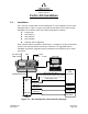

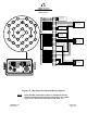
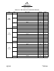
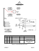
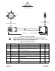
Table Of Contents
- ProTec AIS Hardware Install & Operation Manual
- Table of Contents
- List of Appendixes
- List of Figures
- Figure 1–1. AIS Transponder
- Figure 2–1. AIS Transponder
- Figure 2–2. NAV Display Screen
- Figure 2–3. Own Ship Data Display
- Figure 2–4. AIS Main System Menu
- Figure 2–5. Password Entry Screen
- Figure 2–6. System Information and Configuration Screen
- Figure 2–7. Vessel Data Setup
- Figure 2–8. Channel Management Settings Screen
- Figure 2–9. Antenna Position Screen
- Figure 2–10. Antenna Position Measurements
- Figure 2–11. Safety Text Message
- Figure 2–12. Safety Text Review Screen
- Figure 2–13. Password Change Screen
- Figure 2–14. System Alert Screen
- Figure 2–15. Alarm Status Screen
- Figure 2–16. General Status Screen
- Figure 2–17. Down-Time Log Screen
- Figure 2–18. LCD Viewing Angle Adjust Screen
- Figure 2–19. Baud Rate Setup Screen
- Figure 2–20. AIS Channel Setup Screen
- Figure 3–1. AIS Transponder Interconnection Diagram
- Figure 3–2. IEC Data Cable External Wiring Diagram
- Figure 3–3. AIS Transponder Power Cable
- Figure 3–4. Pilot Port Cable
- Figure 3–5. AIS Transponder Antenna Diagram
- Figure 3–6. AIS Transponder Rear View
- Figure 3–7. AIS Transponder MKD
- Figure 3–8. UAIS Main System Menu
- Figure 3–9. Vessel/Voyage Setup
- Figure 3–10. Antenna Position
- Figure 3–11. Calculating Antenna Position
- Figure 4–1. AIS Transponder O&D Drawing with Trunion Bracket
- Figure 4–2. AIS Transponder O&D Drawing
- Figure 4–3. IEC Data Cable Interconnect Diagram
- List of Tables
- Table 1–1. AIS Parts List
- Table 1–2. Pilot System High-Speed Input Data Formats
- Table 1–3. Pilot System High-Speed Output Data Formats
- Table 1–4. Pilot Port Pinout
- Table 1–5. Long Range Input Data and Formats
- Table 1–6. Long Range Output Data and Formats
- Table 1–7. Sensor Input Data and Formats
- Table 2–1. ProTec AIS Default Passwords
- Table 2–2. Password Type Menu Screen Access
- Table 2–3. Vessel Type Codes
- Table 2–4. Integrity Alarm Conditions Signalled Using ALR Sentence Formatter
- Table 2–5. Sensor Status Indications Signalled Using TXT Sentence Formatter
- Table 3–1. Data Channels
- Table 3–2. IEC Cable and Junction Box Pinouts
- Table 3–3. Pilot Port Pinout
- Table 3–4. ProTec AIS Default Passwords
- Table 3–5. Vessel Type Codes
- Introduction
- General
- Technical Specifications
- AIS Description
- Interface Description
- Data Field Assignments
- GPS and Sensor Input Sentences
- DTM - Datum Reference
- GBS - GNSS Satellite Fault Detection
- GGA - Global Positioning System Fix Data
- GLL - Geographic Position - Latitude / Longitude
- GNS - GNSS Fix Data
- HDT - Heading True
- RMC - Recommended Minimum Specific GNSS Data
- ROT - Rate of Turn
- VBW - Dual Ground / Water Speed
- VTG - Course Over Ground and Ground Speed
- ZDA - Time and Date
- AIS Specific Input Sentences
- GPS and Sensor Input Sentences
- Operation
- Operation
- Minimum Keyboard Display
- Keypad Description
- Data Display Screens
- Data Entry Screens
- AIS Main System Menu
- Logon / Logoff Screen
- System Information and Configuration
- Vessel/Voyage Setup
- Channel Management
- Antenna Position
- Text Messaging
- View Safety Text Log
- Change Password
- System Alert Screen
- Alarm Status
- General Status Screen
- Down-Time Log
- LCD Viewing Angle Adjustment
- Baud Rate Setup
- Set AIS Channels
- Operation
- Installation
- Drawings
- Installation Checklist

Marine Systems
Aviation Recorders
Page 3–7
Initial Issue165M0601-00
Feb. 01/05
The IEC I/O electrical characteristics are as follows:
The “A”, “B” and “C” leads are as defined in IEC 61162–1, 61162–2 and V.11.
“A” and “B” are both signal leads with “C” being the effective return for both the “A”
and “B” leads.
“A” and “B” operate differentially to each other.
High–level output voltage is 4V minimum from the “A” lead to the “C” lead and from
the “B” lead to the “C” lead. Low–level output voltage is 0.4V maximum.
Recommended maximum output current capability is 110mA.
Input is differential from “A” to “B”. Effective input resistance is 4.9k ohm across “A”
and “B” and 96k from “A” or “B” to “C”.
Differential input voltage threshold is 250mV maximum.
Inputs will meet the requirement of withstanding +/–15V between any two leads, “A”,
“B” or “C”.
3.1.2.2 Data Cable
Each transponder will come shipped with an 100 inches long IEC data cable (P/N
024M0599-00) terminated at one end by a J4 connector. (Refer to NO TAG,
Figure 4–3 and Figure 3–2.) The IEC data cable is shielded and contains three
smaller diameter cables, each of which is also shielded. Each of these smaller
cables contains three shielded twisted pairs (STP) each and each STP includes a
drain wire. A low speed unidirectional (input only) data channel (4800 Kbs) is carried
through one STP, and a high speed bidirectional (input/output) data channel (38400
Kbs) will require two pairs.
3.1.2.3 Terminal Block
A terminal block is the preferred installation method for completing the data interface
(NMEA) because data output from a ship sensor ( dGPS, ROT, Gyro) may not sub-
scribe to a standard pinout definition. As such, each installation may require that
the installer identify and cross reference the sensor pinouts with the IEC pinouts,
which is a well defined standard pinout description. The terminal block allows for
greater flexibility in completing the connection to the ship’s sensors.