
User Manual
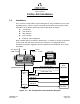
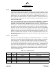

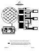
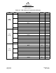
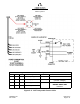
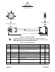
Table Of Contents
- ProTec AIS Hardware Install & Operation Manual
- Table of Contents
- List of Appendixes
- List of Figures
- Figure 1–1. AIS Transponder
- Figure 2–1. AIS Transponder
- Figure 2–2. NAV Display Screen
- Figure 2–3. Own Ship Data Display
- Figure 2–4. AIS Main System Menu
- Figure 2–5. Password Entry Screen
- Figure 2–6. System Information and Configuration Screen
- Figure 2–7. Vessel Data Setup
- Figure 2–8. Channel Management Settings Screen
- Figure 2–9. Antenna Position Screen
- Figure 2–10. Antenna Position Measurements
- Figure 2–11. Safety Text Message
- Figure 2–12. Safety Text Review Screen
- Figure 2–13. Password Change Screen
- Figure 2–14. System Alert Screen
- Figure 2–15. Alarm Status Screen
- Figure 2–16. General Status Screen
- Figure 2–17. Down-Time Log Screen
- Figure 2–18. LCD Viewing Angle Adjust Screen
- Figure 2–19. Baud Rate Setup Screen
- Figure 2–20. AIS Channel Setup Screen
- Figure 3–1. AIS Transponder Interconnection Diagram
- Figure 3–2. IEC Data Cable External Wiring Diagram
- Figure 3–3. AIS Transponder Power Cable
- Figure 3–4. Pilot Port Cable
- Figure 3–5. AIS Transponder Antenna Diagram
- Figure 3–6. AIS Transponder Rear View
- Figure 3–7. AIS Transponder MKD
- Figure 3–8. UAIS Main System Menu
- Figure 3–9. Vessel/Voyage Setup
- Figure 3–10. Antenna Position
- Figure 3–11. Calculating Antenna Position
- Figure 4–1. AIS Transponder O&D Drawing with Trunion Bracket
- Figure 4–2. AIS Transponder O&D Drawing
- Figure 4–3. IEC Data Cable Interconnect Diagram
- List of Tables
- Table 1–1. AIS Parts List
- Table 1–2. Pilot System High-Speed Input Data Formats
- Table 1–3. Pilot System High-Speed Output Data Formats
- Table 1–4. Pilot Port Pinout
- Table 1–5. Long Range Input Data and Formats
- Table 1–6. Long Range Output Data and Formats
- Table 1–7. Sensor Input Data and Formats
- Table 2–1. ProTec AIS Default Passwords
- Table 2–2. Password Type Menu Screen Access
- Table 2–3. Vessel Type Codes
- Table 2–4. Integrity Alarm Conditions Signalled Using ALR Sentence Formatter
- Table 2–5. Sensor Status Indications Signalled Using TXT Sentence Formatter
- Table 3–1. Data Channels
- Table 3–2. IEC Cable and Junction Box Pinouts
- Table 3–3. Pilot Port Pinout
- Table 3–4. ProTec AIS Default Passwords
- Table 3–5. Vessel Type Codes
- Introduction
- General
- Technical Specifications
- AIS Description
- Interface Description
- Data Field Assignments
- GPS and Sensor Input Sentences
- DTM - Datum Reference
- GBS - GNSS Satellite Fault Detection
- GGA - Global Positioning System Fix Data
- GLL - Geographic Position - Latitude / Longitude
- GNS - GNSS Fix Data
- HDT - Heading True
- RMC - Recommended Minimum Specific GNSS Data
- ROT - Rate of Turn
- VBW - Dual Ground / Water Speed
- VTG - Course Over Ground and Ground Speed
- ZDA - Time and Date
- AIS Specific Input Sentences
- GPS and Sensor Input Sentences
- Operation
- Operation
- Minimum Keyboard Display
- Keypad Description
- Data Display Screens
- Data Entry Screens
- AIS Main System Menu
- Logon / Logoff Screen
- System Information and Configuration
- Vessel/Voyage Setup
- Channel Management
- Antenna Position
- Text Messaging
- View Safety Text Log
- Change Password
- System Alert Screen
- Alarm Status
- General Status Screen
- Down-Time Log
- LCD Viewing Angle Adjustment
- Baud Rate Setup
- Set AIS Channels
- Operation
- Installation
- Drawings
- Installation Checklist

Marine Systems
Aviation Recorders
Page 3–6
Initial Issue 165M0601-00
Feb. 01/05
3.1.2. Connecting the IEC Data Interface Cable
The AIS Transponder receives data from the ship’s sensors through a data interface
cable which is connected to the back of the transponder through a data port. IMO
regulations require that the ship heading, speed–over–ground (SOG), course–over–
ground (COG), rate–of–turn (ROT) and position be transmitted from the AIS. In or-
der to meet these requirements, the L-3 ProTec provides six (6) data channels to al-
low the AIS to be connected to the ships Gyrocompass and DGPS system in accor-
dance with NMEA 0183.
The L3 AIS is shipped with one IEC interface cable P/N 024M0599-00. All IEC/Pilot
communications with the AIS is referenced with the L-3 ProTec considered the
“MASTER” in that transmit data is OUTPUT from the L-3 ProTec, and receive data is
INPUT to the L-3 ProTec. All channels are isolated with individual shielded twisted
pair cables. For more inforomation, refer to Figure 4–3. The IEC connector (J4) is
located on the back of the L-3 ProTec. (Refer to IEC 61993–2 annex D. and NMEA
0183) IEC channels 1, 2, and 3 are RECEIVE ONLY sensor inputs. Differential data
(RS422) is received on each of these channels and internally converted to TTL for
input to a standard UART. Channels 4, 5, and 8 are all RS422 interfaces. IEC chan-
nels 4 and 5 are TRANSMIT/RECEIVE channels for AIS data. IEC channel 8 is the
AIS long range port.
3.1.2.1 Data Channels
Data enters the Transponder through six (6) available data channels. Three data
channels are low speed unidirectional (4800 baud) channels suitable for data input
to the transponder. The other three data channels are high speed bidirectional
channels (38400 baud) which support both input and output to/from the transponder.
The channels are described below by channel number and type. Suggested uses of
each channel are provided but it is not required that a user define the channels in
this fashion. The internal software in the transponder is able to distinguish the type
of data feeding from each channel provided all data streams subscribe to the IEC
61162 format (NMEA 0183).
Table 3–1. Data Channels
Channel BAUD Type Suggested Use
1 4800 Receive dGPS (COG, SOG, LAT, LON)
2 4800 Receive Rate of Turn
3 4800 Receive Heading (Gyro)
4 38400 Transmit / Receive PC Application
5 38400 Transmit / Receive ARPA/ECDIS
8 38400 Transmit / Receive Long Range Tracking (Dedicated)