
User Manual
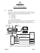

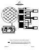
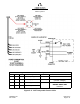
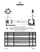
Table Of Contents
- ProTec AIS Hardware Install & Operation Manual
- Table of Contents
- List of Appendixes
- List of Figures
- Figure 1–1. AIS Transponder
- Figure 2–1. AIS Transponder
- Figure 2–2. NAV Display Screen
- Figure 2–3. Own Ship Data Display
- Figure 2–4. AIS Main System Menu
- Figure 2–5. Password Entry Screen
- Figure 2–6. System Information and Configuration Screen
- Figure 2–7. Vessel Data Setup
- Figure 2–8. Channel Management Settings Screen
- Figure 2–9. Antenna Position Screen
- Figure 2–10. Antenna Position Measurements
- Figure 2–11. Safety Text Message
- Figure 2–12. Safety Text Review Screen
- Figure 2–13. Password Change Screen
- Figure 2–14. System Alert Screen
- Figure 2–15. Alarm Status Screen
- Figure 2–16. General Status Screen
- Figure 2–17. Down-Time Log Screen
- Figure 2–18. LCD Viewing Angle Adjust Screen
- Figure 2–19. Baud Rate Setup Screen
- Figure 2–20. AIS Channel Setup Screen
- Figure 3–1. AIS Transponder Interconnection Diagram
- Figure 3–2. IEC Data Cable External Wiring Diagram
- Figure 3–3. AIS Transponder Power Cable
- Figure 3–4. Pilot Port Cable
- Figure 3–5. AIS Transponder Antenna Diagram
- Figure 3–6. AIS Transponder Rear View
- Figure 3–7. AIS Transponder MKD
- Figure 3–8. UAIS Main System Menu
- Figure 3–9. Vessel/Voyage Setup
- Figure 3–10. Antenna Position
- Figure 3–11. Calculating Antenna Position
- Figure 4–1. AIS Transponder O&D Drawing with Trunion Bracket
- Figure 4–2. AIS Transponder O&D Drawing
- Figure 4–3. IEC Data Cable Interconnect Diagram
- List of Tables
- Table 1–1. AIS Parts List
- Table 1–2. Pilot System High-Speed Input Data Formats
- Table 1–3. Pilot System High-Speed Output Data Formats
- Table 1–4. Pilot Port Pinout
- Table 1–5. Long Range Input Data and Formats
- Table 1–6. Long Range Output Data and Formats
- Table 1–7. Sensor Input Data and Formats
- Table 2–1. ProTec AIS Default Passwords
- Table 2–2. Password Type Menu Screen Access
- Table 2–3. Vessel Type Codes
- Table 2–4. Integrity Alarm Conditions Signalled Using ALR Sentence Formatter
- Table 2–5. Sensor Status Indications Signalled Using TXT Sentence Formatter
- Table 3–1. Data Channels
- Table 3–2. IEC Cable and Junction Box Pinouts
- Table 3–3. Pilot Port Pinout
- Table 3–4. ProTec AIS Default Passwords
- Table 3–5. Vessel Type Codes
- Introduction
- General
- Technical Specifications
- AIS Description
- Interface Description
- Data Field Assignments
- GPS and Sensor Input Sentences
- DTM - Datum Reference
- GBS - GNSS Satellite Fault Detection
- GGA - Global Positioning System Fix Data
- GLL - Geographic Position - Latitude / Longitude
- GNS - GNSS Fix Data
- HDT - Heading True
- RMC - Recommended Minimum Specific GNSS Data
- ROT - Rate of Turn
- VBW - Dual Ground / Water Speed
- VTG - Course Over Ground and Ground Speed
- ZDA - Time and Date
- AIS Specific Input Sentences
- GPS and Sensor Input Sentences
- Operation
- Operation
- Minimum Keyboard Display
- Keypad Description
- Data Display Screens
- Data Entry Screens
- AIS Main System Menu
- Logon / Logoff Screen
- System Information and Configuration
- Vessel/Voyage Setup
- Channel Management
- Antenna Position
- Text Messaging
- View Safety Text Log
- Change Password
- System Alert Screen
- Alarm Status
- General Status Screen
- Down-Time Log
- LCD Viewing Angle Adjustment
- Baud Rate Setup
- Set AIS Channels
- Operation
- Installation
- Drawings
- Installation Checklist

Marine Systems
Aviation Recorders
Page 3–4
Initial Issue 165M0601-00
Feb. 01/05
3.1.1. Transponder
The L-3 ProTec is a single box design which is easily installed into any existing
bridge layout. The compact design requires minimal clearance (refer to Section 4
Figure 4–1 and Figure 4–2) and can be mounted in a trunion bracket or mounted
flush using the available flush–mount bracket.
F Mount the transponder in a position which provides easy access to the key-
board and display.
F If using the trunion bracket, the mount itself may be used to mark the screw
holes on the mounting surface. When locating the transponder, consider that
the IMO mandates that the AIS keyboard and display be easily accessed from
a navigable position on the bridge.
F If used, Mount the transponder in the trunion utilizing the trunion knobs pro-
vided, otherwise mount transponder in flush mount bracket.
F Locate and mount the terminal block or junction box in a position near the
transponder. The IEC cable provided with the unit is 100 inches (2.54 m) long.
Locate the terminal block in a fashion which allows for easy access to the termi-
nals for making the connections to required input/output feeds.
F When connecting the power cable, the “Red“ lead goes to positive and “Black“
to negative. Ensure proper ground wire attachment to ships structure. The oth-
er two leads can be used to connect to an external alarm system. This alarm
system can provide an audio and/or visual alarm in the event of an internal sys-
tem malfunction, or if the AIS loses power or is turned off.
Install the transponder, and complete the AIS Installation Checklist found it Ap-
pendix A, as follows:
(1) Mount the transponder. (In trunion, if used.)
NOTE
: A junction box may be used in place of the terminal block.
(2) Locate an ideal position for the terminal block.
F Protected from weather.
F Protected from high heat.
F Protected from accidental contact with conductive material.
F Within 100 inches (2.5 m) of the transponder due to IEC data cable length.
F Grounding of terminal block to ship’s structure.
F Need to feed cables from navigational sensors.
(3) Mount terminal block or junction box with self tapping screws.
(4) Ground terminal block to ship’s structure using grounding cable provided.