
User Manual
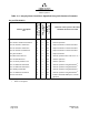
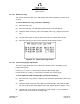


Table Of Contents
- ProTec AIS Hardware Install & Operation Manual
- Table of Contents
- List of Appendixes
- List of Figures
- Figure 1–1. AIS Transponder
- Figure 2–1. AIS Transponder
- Figure 2–2. NAV Display Screen
- Figure 2–3. Own Ship Data Display
- Figure 2–4. AIS Main System Menu
- Figure 2–5. Password Entry Screen
- Figure 2–6. System Information and Configuration Screen
- Figure 2–7. Vessel Data Setup
- Figure 2–8. Channel Management Settings Screen
- Figure 2–9. Antenna Position Screen
- Figure 2–10. Antenna Position Measurements
- Figure 2–11. Safety Text Message
- Figure 2–12. Safety Text Review Screen
- Figure 2–13. Password Change Screen
- Figure 2–14. System Alert Screen
- Figure 2–15. Alarm Status Screen
- Figure 2–16. General Status Screen
- Figure 2–17. Down-Time Log Screen
- Figure 2–18. LCD Viewing Angle Adjust Screen
- Figure 2–19. Baud Rate Setup Screen
- Figure 2–20. AIS Channel Setup Screen
- Figure 3–1. AIS Transponder Interconnection Diagram
- Figure 3–2. IEC Data Cable External Wiring Diagram
- Figure 3–3. AIS Transponder Power Cable
- Figure 3–4. Pilot Port Cable
- Figure 3–5. AIS Transponder Antenna Diagram
- Figure 3–6. AIS Transponder Rear View
- Figure 3–7. AIS Transponder MKD
- Figure 3–8. UAIS Main System Menu
- Figure 3–9. Vessel/Voyage Setup
- Figure 3–10. Antenna Position
- Figure 3–11. Calculating Antenna Position
- Figure 4–1. AIS Transponder O&D Drawing with Trunion Bracket
- Figure 4–2. AIS Transponder O&D Drawing
- Figure 4–3. IEC Data Cable Interconnect Diagram
- List of Tables
- Table 1–1. AIS Parts List
- Table 1–2. Pilot System High-Speed Input Data Formats
- Table 1–3. Pilot System High-Speed Output Data Formats
- Table 1–4. Pilot Port Pinout
- Table 1–5. Long Range Input Data and Formats
- Table 1–6. Long Range Output Data and Formats
- Table 1–7. Sensor Input Data and Formats
- Table 2–1. ProTec AIS Default Passwords
- Table 2–2. Password Type Menu Screen Access
- Table 2–3. Vessel Type Codes
- Table 2–4. Integrity Alarm Conditions Signalled Using ALR Sentence Formatter
- Table 2–5. Sensor Status Indications Signalled Using TXT Sentence Formatter
- Table 3–1. Data Channels
- Table 3–2. IEC Cable and Junction Box Pinouts
- Table 3–3. Pilot Port Pinout
- Table 3–4. ProTec AIS Default Passwords
- Table 3–5. Vessel Type Codes
- Introduction
- General
- Technical Specifications
- AIS Description
- Interface Description
- Data Field Assignments
- GPS and Sensor Input Sentences
- DTM - Datum Reference
- GBS - GNSS Satellite Fault Detection
- GGA - Global Positioning System Fix Data
- GLL - Geographic Position - Latitude / Longitude
- GNS - GNSS Fix Data
- HDT - Heading True
- RMC - Recommended Minimum Specific GNSS Data
- ROT - Rate of Turn
- VBW - Dual Ground / Water Speed
- VTG - Course Over Ground and Ground Speed
- ZDA - Time and Date
- AIS Specific Input Sentences
- GPS and Sensor Input Sentences
- Operation
- Operation
- Minimum Keyboard Display
- Keypad Description
- Data Display Screens
- Data Entry Screens
- AIS Main System Menu
- Logon / Logoff Screen
- System Information and Configuration
- Vessel/Voyage Setup
- Channel Management
- Antenna Position
- Text Messaging
- View Safety Text Log
- Change Password
- System Alert Screen
- Alarm Status
- General Status Screen
- Down-Time Log
- LCD Viewing Angle Adjustment
- Baud Rate Setup
- Set AIS Channels
- Operation
- Installation
- Drawings
- Installation Checklist

Marine Systems
Aviation Recorders
Page 2–24
Initial Issue 165M0601-00
Feb. 01/05
Table 2–4. Integrity Alarm Conditions Signalled Using ALR Sentence Formatter
Alarm’s description
text
Alarm condition
threshold exceeded
Alarm condition
exceeded
Alarm ID
Text Identifier
Reaction of the system to the alarm
condition threshold exceeded
AIS: Tx malfunction A V 001 Stop transmission
AIS: Antenna VSWR exceeds limit A V 002 Continue operation
AIS: Rx channel 1 malfunction A V 003 Stop transmission on affected channel
AIS: Rx channel 2 malfunction A V 004 Stop transmission on affected channel
AIS: Rx channel 70 malfunction A V 005 Stop transmission on affected channel
AIS: general failure A V 006 Stop transmission
AIS: MKD connection lost A V 008 continue operation with “DTE” set to “1”
AIS: external EPFS lost A V 025 continue operation
AIS: no sensor position in use A V 026 continue operation
AIS: no valid SOG information A V 029 continue operation using default data
AIS: no valid COG information A V 030 continue operation using default data
AIS: Heading lost/invalid A V 032 continue operation using default data
AIS: no valid ROT information A V 035 continue operation using default data
AIS: IEC Com Error A V 051 indicates miswired NMEA port, continue
operation
1
2
2
2
2
1
If applicable
2
When so configured
As per IEC 61193–2