
User Manual
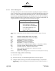
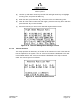
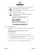
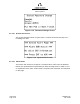
Table Of Contents
- ProTec AIS Hardware Install & Operation Manual
- Table of Contents
- List of Appendixes
- List of Figures
- Figure 1–1. AIS Transponder
- Figure 2–1. AIS Transponder
- Figure 2–2. NAV Display Screen
- Figure 2–3. Own Ship Data Display
- Figure 2–4. AIS Main System Menu
- Figure 2–5. Password Entry Screen
- Figure 2–6. System Information and Configuration Screen
- Figure 2–7. Vessel Data Setup
- Figure 2–8. Channel Management Settings Screen
- Figure 2–9. Antenna Position Screen
- Figure 2–10. Antenna Position Measurements
- Figure 2–11. Safety Text Message
- Figure 2–12. Safety Text Review Screen
- Figure 2–13. Password Change Screen
- Figure 2–14. System Alert Screen
- Figure 2–15. Alarm Status Screen
- Figure 2–16. General Status Screen
- Figure 2–17. Down-Time Log Screen
- Figure 2–18. LCD Viewing Angle Adjust Screen
- Figure 2–19. Baud Rate Setup Screen
- Figure 2–20. AIS Channel Setup Screen
- Figure 3–1. AIS Transponder Interconnection Diagram
- Figure 3–2. IEC Data Cable External Wiring Diagram
- Figure 3–3. AIS Transponder Power Cable
- Figure 3–4. Pilot Port Cable
- Figure 3–5. AIS Transponder Antenna Diagram
- Figure 3–6. AIS Transponder Rear View
- Figure 3–7. AIS Transponder MKD
- Figure 3–8. UAIS Main System Menu
- Figure 3–9. Vessel/Voyage Setup
- Figure 3–10. Antenna Position
- Figure 3–11. Calculating Antenna Position
- Figure 4–1. AIS Transponder O&D Drawing with Trunion Bracket
- Figure 4–2. AIS Transponder O&D Drawing
- Figure 4–3. IEC Data Cable Interconnect Diagram
- List of Tables
- Table 1–1. AIS Parts List
- Table 1–2. Pilot System High-Speed Input Data Formats
- Table 1–3. Pilot System High-Speed Output Data Formats
- Table 1–4. Pilot Port Pinout
- Table 1–5. Long Range Input Data and Formats
- Table 1–6. Long Range Output Data and Formats
- Table 1–7. Sensor Input Data and Formats
- Table 2–1. ProTec AIS Default Passwords
- Table 2–2. Password Type Menu Screen Access
- Table 2–3. Vessel Type Codes
- Table 2–4. Integrity Alarm Conditions Signalled Using ALR Sentence Formatter
- Table 2–5. Sensor Status Indications Signalled Using TXT Sentence Formatter
- Table 3–1. Data Channels
- Table 3–2. IEC Cable and Junction Box Pinouts
- Table 3–3. Pilot Port Pinout
- Table 3–4. ProTec AIS Default Passwords
- Table 3–5. Vessel Type Codes
- Introduction
- General
- Technical Specifications
- AIS Description
- Interface Description
- Data Field Assignments
- GPS and Sensor Input Sentences
- DTM - Datum Reference
- GBS - GNSS Satellite Fault Detection
- GGA - Global Positioning System Fix Data
- GLL - Geographic Position - Latitude / Longitude
- GNS - GNSS Fix Data
- HDT - Heading True
- RMC - Recommended Minimum Specific GNSS Data
- ROT - Rate of Turn
- VBW - Dual Ground / Water Speed
- VTG - Course Over Ground and Ground Speed
- ZDA - Time and Date
- AIS Specific Input Sentences
- GPS and Sensor Input Sentences
- Operation
- Operation
- Minimum Keyboard Display
- Keypad Description
- Data Display Screens
- Data Entry Screens
- AIS Main System Menu
- Logon / Logoff Screen
- System Information and Configuration
- Vessel/Voyage Setup
- Channel Management
- Antenna Position
- Text Messaging
- View Safety Text Log
- Change Password
- System Alert Screen
- Alarm Status
- General Status Screen
- Down-Time Log
- LCD Viewing Angle Adjustment
- Baud Rate Setup
- Set AIS Channels
- Operation
- Installation
- Drawings
- Installation Checklist

Marine Systems
Aviation Recorders
Page 2–16
Initial Issue 165M0601-00
Feb. 01/05
2.1.4.5 Channel Management
This page displays all of the relevant information regarding the regions established
either by manual entry, a governing authority’s VTS station broadcasting region infor-
mation, or another Universal AIS broadcasting the data. These regions determine
the authorized operating frequencies for the coverage area. The user can set these
different configurations at the initial setup; however, the L-3 ProTec Transponder will
acquire the data for a new region once it has entered the region.
Edit Chan Mgmt Settings
NE: N 91’00.0 E 181’00.0
SW: N 91’00.0 E 181’00.0
ChA: 2087 Bw0 ChB:2088 Bw0
PLvl:H Md:TxRxAB TZn: Nm
Src:Intrnl MMSI:---------
FNC: ← Prv. → Nxt. FNC Save
Press FNC → NAV button from any menu and use the up (↑) or down (↓) arrow
keys.
NE: Indicates the North East corner of the region.
SW: Indicates the South West corner of the region.
ChA: Channel Frequency for Channel A.
Bw: Bandwidth 0 = 25 kHz, 1 = 12.5 kHz.
ChB: Channel Frequency for Channel B.
Bw: Bandwidth 0 = 25 kHz, 1 = 12.5 kHz.
Plvl: Power Level H = high power (12.5 Watts), L = low power (2 Watts)
Md: TxRxAB, TARxAB, TBRxAB, RxAB, RAOnly, and RBOnly.
TZn: Transition zone size, defined in nautical miles.
Src: Intrnl = Internal command, Extrnl = External command
(governing authority).
MMSI: MMSI of the authority that has issued the command (blank if internal).
For the initial setup perform the following:
(1) Press the FNC key.
(2) Press the NAV key. The AIS Main System Menu screen will appear.
(3) Using the down Arrow key, select “Edit Chan Mgmt Settings”, and press the
ENT key. The Channel Management Table Entry screen will appear. (Refer to
Figure 2–8.)