
User Manual
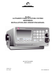

Table Of Contents
- ProTec AIS Hardware Install & Operation Manual
- Table of Contents
- List of Appendixes
- List of Figures
- Figure 1–1. AIS Transponder
- Figure 2–1. AIS Transponder
- Figure 2–2. NAV Display Screen
- Figure 2–3. Own Ship Data Display
- Figure 2–4. AIS Main System Menu
- Figure 2–5. Password Entry Screen
- Figure 2–6. System Information and Configuration Screen
- Figure 2–7. Vessel Data Setup
- Figure 2–8. Channel Management Settings Screen
- Figure 2–9. Antenna Position Screen
- Figure 2–10. Antenna Position Measurements
- Figure 2–11. Safety Text Message
- Figure 2–12. Safety Text Review Screen
- Figure 2–13. Password Change Screen
- Figure 2–14. System Alert Screen
- Figure 2–15. Alarm Status Screen
- Figure 2–16. General Status Screen
- Figure 2–17. Down-Time Log Screen
- Figure 2–18. LCD Viewing Angle Adjust Screen
- Figure 2–19. Baud Rate Setup Screen
- Figure 2–20. AIS Channel Setup Screen
- Figure 3–1. AIS Transponder Interconnection Diagram
- Figure 3–2. IEC Data Cable External Wiring Diagram
- Figure 3–3. AIS Transponder Power Cable
- Figure 3–4. Pilot Port Cable
- Figure 3–5. AIS Transponder Antenna Diagram
- Figure 3–6. AIS Transponder Rear View
- Figure 3–7. AIS Transponder MKD
- Figure 3–8. UAIS Main System Menu
- Figure 3–9. Vessel/Voyage Setup
- Figure 3–10. Antenna Position
- Figure 3–11. Calculating Antenna Position
- Figure 4–1. AIS Transponder O&D Drawing with Trunion Bracket
- Figure 4–2. AIS Transponder O&D Drawing
- Figure 4–3. IEC Data Cable Interconnect Diagram
- List of Tables
- Table 1–1. AIS Parts List
- Table 1–2. Pilot System High-Speed Input Data Formats
- Table 1–3. Pilot System High-Speed Output Data Formats
- Table 1–4. Pilot Port Pinout
- Table 1–5. Long Range Input Data and Formats
- Table 1–6. Long Range Output Data and Formats
- Table 1–7. Sensor Input Data and Formats
- Table 2–1. ProTec AIS Default Passwords
- Table 2–2. Password Type Menu Screen Access
- Table 2–3. Vessel Type Codes
- Table 2–4. Integrity Alarm Conditions Signalled Using ALR Sentence Formatter
- Table 2–5. Sensor Status Indications Signalled Using TXT Sentence Formatter
- Table 3–1. Data Channels
- Table 3–2. IEC Cable and Junction Box Pinouts
- Table 3–3. Pilot Port Pinout
- Table 3–4. ProTec AIS Default Passwords
- Table 3–5. Vessel Type Codes
- Introduction
- General
- Technical Specifications
- AIS Description
- Interface Description
- Data Field Assignments
- GPS and Sensor Input Sentences
- DTM - Datum Reference
- GBS - GNSS Satellite Fault Detection
- GGA - Global Positioning System Fix Data
- GLL - Geographic Position - Latitude / Longitude
- GNS - GNSS Fix Data
- HDT - Heading True
- RMC - Recommended Minimum Specific GNSS Data
- ROT - Rate of Turn
- VBW - Dual Ground / Water Speed
- VTG - Course Over Ground and Ground Speed
- ZDA - Time and Date
- AIS Specific Input Sentences
- GPS and Sensor Input Sentences
- Operation
- Operation
- Minimum Keyboard Display
- Keypad Description
- Data Display Screens
- Data Entry Screens
- AIS Main System Menu
- Logon / Logoff Screen
- System Information and Configuration
- Vessel/Voyage Setup
- Channel Management
- Antenna Position
- Text Messaging
- View Safety Text Log
- Change Password
- System Alert Screen
- Alarm Status
- General Status Screen
- Down-Time Log
- LCD Viewing Angle Adjustment
- Baud Rate Setup
- Set AIS Channels
- Operation
- Installation
- Drawings
- Installation Checklist

Marine Systems
Aviation Recorders
Page v
Initial Issue165M0601-00
Feb. 01/05
RETURN OF MATERIAL UNDER WARRANTY
1. Material should be returned to the following address:
L–3 COMMUNICATIONS CORPORATION
AVIATION RECORDERS DIVISION
6000 E. Fruitville Road
Sarasota, FL 34232
Attn: WARRANTY RETURNS
2. For returning overseas shipments, the following customs broker must be used:
L–3 COMMUNICATIONS CORPORATION
AVIATION RECORDERS DIVISION
c/o A.J. Arango
Air Cargo Bldg.
Hoover Blvd.
Tampa Int’l Airport
Tampa, Florida 33634
Tel: (813) 248–9220
Fax: (813) 248–6013
To ensure prompt handling of material returned under warranty, your return order and shipment should clearly
identify the item as a warranty return, and a copy of such return order should accompany the shipment. Status of
warranty in process will be provided by the Warranty Administrator.
3. Warranty claims and warranty return orders pertaining to components and spare parts returned should be
mailed to the following address:
L–3 COMMUNICATIONS CORPORATION
AVIATION RECORDERS DIVISION
P. O. Box 3041
Sarasota, FL 34230–3041
Attn: Marine Systems Warranty Administrator
Tel: (941) 377–5574
Fax: (941) 377–5591
RETURNED GOODS
Goods returned to stock for credit at the request of the Buyer and authorized by the Seller, will be subject to a restock-
ing charge of 10% of the purchase price if notified within 30 days of the order, and 25% of the purchase price if notified
after 30 days of the order.
CANCELLATION CHARGE
Any order wishing to be canceled must be approved by the pertinent Account Administrator and may be accountable
for a cancellation fee of 15%. This cancellation fee shall take into account expenses already incurred and commit-
ments made by L–3.