
User Manual
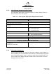
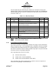
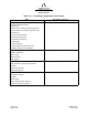
Table Of Contents
- ProTec AIS Hardware Install & Operation Manual
- Table of Contents
- List of Appendixes
- List of Figures
- Figure 1–1. AIS Transponder
- Figure 2–1. AIS Transponder
- Figure 2–2. NAV Display Screen
- Figure 2–3. Own Ship Data Display
- Figure 2–4. AIS Main System Menu
- Figure 2–5. Password Entry Screen
- Figure 2–6. System Information and Configuration Screen
- Figure 2–7. Vessel Data Setup
- Figure 2–8. Channel Management Settings Screen
- Figure 2–9. Antenna Position Screen
- Figure 2–10. Antenna Position Measurements
- Figure 2–11. Safety Text Message
- Figure 2–12. Safety Text Review Screen
- Figure 2–13. Password Change Screen
- Figure 2–14. System Alert Screen
- Figure 2–15. Alarm Status Screen
- Figure 2–16. General Status Screen
- Figure 2–17. Down-Time Log Screen
- Figure 2–18. LCD Viewing Angle Adjust Screen
- Figure 2–19. Baud Rate Setup Screen
- Figure 2–20. AIS Channel Setup Screen
- Figure 3–1. AIS Transponder Interconnection Diagram
- Figure 3–2. IEC Data Cable External Wiring Diagram
- Figure 3–3. AIS Transponder Power Cable
- Figure 3–4. Pilot Port Cable
- Figure 3–5. AIS Transponder Antenna Diagram
- Figure 3–6. AIS Transponder Rear View
- Figure 3–7. AIS Transponder MKD
- Figure 3–8. UAIS Main System Menu
- Figure 3–9. Vessel/Voyage Setup
- Figure 3–10. Antenna Position
- Figure 3–11. Calculating Antenna Position
- Figure 4–1. AIS Transponder O&D Drawing with Trunion Bracket
- Figure 4–2. AIS Transponder O&D Drawing
- Figure 4–3. IEC Data Cable Interconnect Diagram
- List of Tables
- Table 1–1. AIS Parts List
- Table 1–2. Pilot System High-Speed Input Data Formats
- Table 1–3. Pilot System High-Speed Output Data Formats
- Table 1–4. Pilot Port Pinout
- Table 1–5. Long Range Input Data and Formats
- Table 1–6. Long Range Output Data and Formats
- Table 1–7. Sensor Input Data and Formats
- Table 2–1. ProTec AIS Default Passwords
- Table 2–2. Password Type Menu Screen Access
- Table 2–3. Vessel Type Codes
- Table 2–4. Integrity Alarm Conditions Signalled Using ALR Sentence Formatter
- Table 2–5. Sensor Status Indications Signalled Using TXT Sentence Formatter
- Table 3–1. Data Channels
- Table 3–2. IEC Cable and Junction Box Pinouts
- Table 3–3. Pilot Port Pinout
- Table 3–4. ProTec AIS Default Passwords
- Table 3–5. Vessel Type Codes
- Introduction
- General
- Technical Specifications
- AIS Description
- Interface Description
- Data Field Assignments
- GPS and Sensor Input Sentences
- DTM - Datum Reference
- GBS - GNSS Satellite Fault Detection
- GGA - Global Positioning System Fix Data
- GLL - Geographic Position - Latitude / Longitude
- GNS - GNSS Fix Data
- HDT - Heading True
- RMC - Recommended Minimum Specific GNSS Data
- ROT - Rate of Turn
- VBW - Dual Ground / Water Speed
- VTG - Course Over Ground and Ground Speed
- ZDA - Time and Date
- AIS Specific Input Sentences
- GPS and Sensor Input Sentences
- Operation
- Operation
- Minimum Keyboard Display
- Keypad Description
- Data Display Screens
- Data Entry Screens
- AIS Main System Menu
- Logon / Logoff Screen
- System Information and Configuration
- Vessel/Voyage Setup
- Channel Management
- Antenna Position
- Text Messaging
- View Safety Text Log
- Change Password
- System Alert Screen
- Alarm Status
- General Status Screen
- Down-Time Log
- LCD Viewing Angle Adjustment
- Baud Rate Setup
- Set AIS Channels
- Operation
- Installation
- Drawings
- Installation Checklist

Marine Systems
Aviation Recorders
Page 1–15
Initial Issue165M0601-00
Feb. 01/05
The Pilot input/output port defined by IEC 61193-2 for connections of ship’s pilot
equipment shall, if fitted, be connected using the pilot port cable, p/n: 024M0099-03.
The Pilot input/output port meets the requirement of IEC 61162-2 and is terminated
as shown in Table 1–4.
Table 1–4. Pilot Port Pinout
J1 Pin Name Description Pair Color P2 Pin
1 PILOT_TXA RS4–22 Compliant Output A Blue 2
2 GND Signal/Power 0 Volt Reference Black 5
3 + 8V
+ 8.0 Volt ( 5%) Output Used to Power External
Test Equipment. External Equipment should be
Current Limited to 300mA
4 PILOT_TXB RS–422 Compliant Output B Black 7
5 PILOT_RXA RS–422 Compliant Input A Green 8
6 PILOT_RXB RS–422 Compliant Input B Black 3
7 TRACE/BOOT_TX TTL–Level RS–232 Serial Output (Trace Message/
Bootload Output)
8 RX_SINAD TDMA / DSC FM Discriminator Output used to
Test Receiver Performance during Special Test
Modes.
9 NO CONNECT Not Used
NOTE: Some early transponders had incorrect Pilot Port wiring.
See factory for more details.
1.4.4. Long Range Equipment Interface
The range of operation of standard AIS is limited to the range of VHF transmissions
which is around 30 miles. The Long Range mode is intended to allow the exchange
of ships position information from ship to a competent authority via a satellite inter-
face such as Inmarsat-C which is already onboard many ships. This port is intended
to interface with the Long Range equipment.
The Long Range reply can be set in either:
F automatic mode (AUTO)
F manual mode L-3 ProTec (MANUAL)
F manual mode external application (EXT APPL).
The Long Range reply, when in AUTO mode, is made as soon as a request is re-
ceived on the Long Range communication port.