
User's Manual

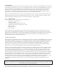


The signal bandwidth also limits the channels that may be selected since the FCC Rules prohibit the spectrum
from extending beyond the 902 to 928MHz boundaries. Thus the narrower bandwidth signals may be assigned
channels that are closer to these limits, as shown in Table 2. The bandpass filters at the front end of the
NovaRoam™ 900 receiver also limit channel selection. Nova Engineering has deliberately selected a relatively
narrow filter bandwidth in order to block interference from neighboring frequency bands such as pagers. This
enables the NovaRoam™ 900 to establish robust links between sites that would otherwise be disabled by strong
adjacent channel interference.
The NovaRoam™ 900 transceiver antenna port mates to one of three special types of antennas and coaxial cable
assemblies. The user is cautioned against attempting to substitute antennas or cable assemblies that have not
been explicitly authorized by Nova Engineering since this could result in noncompliant performance, in
violation of the Part 15 Rules drafted by the FCC. This circumstance has led Nova Engineering to select a
nonstandard antenna port connector, RP-TNC, to prevent improper antennas and cable assemblies from being
employed. The following three configurations have been tested by Nova Engineering and approved for use
with the NovaRoam™ 900 transceiver:
1. Collinear Whip: Antenex BB8965C with Antenex GMBD magnetic mount [Nova P/N 8040-0119]
2. Omni: Antenex FG9026 with 25’ LMR400 cable assembly [Nova P/N 8040-0117]
3. Yagi: Antenex YB8966 with 100’ LMR400 cable assembly [Nova P/N 8040-0118].
A collinear whip antenna is supplied with the purchase of each NovaRoam™ 900 transceiver. The whip attaches
to a magnetic mount that includes an integral 12’ coaxial cable. The whip and magnetic mount combination is
supplied as a custom assembly by Nova Engineering, P/N 8040-0119, that includes an RP-TNC connector to
mate directly to the NovaRoam™ 900 antenna port. Orient the antenna during installation so that it stands
vertically, thereby providing an omnidirectional pattern.
The omni and Yagi antennas are selected for situations that demand extended range from the NovaRoam™ 900
transceiver. Each antenna is supplied with a special coaxial cable assembly, Nova P/N 8040-0117 or 8040-0118,
that has been designed to yield FCC compliant performance from the NovaRoam™ 900. The attenuation of each
cable assembly compensates for the increased gain of these antennas. Such cable assemblies can also be used to
elevate the antennas on masts to further increase the NovaRoam™ 900 range. Raising the antenna is one of the
most effective methods of improving marginal links. The 25’ and 100’ cable assemblies are specified for the
omni and Yagi antenna, respectively. The longer cable assembly may also be used for the omni antenna,
although this would decrease the system margin by 3dB. However, the shorter cable assembly is not authorized
for the Yagi antenna since it yields radiated RF power levels in violation of the Part 15 Rules established by the
FCC.
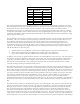
The omni antenna produces an omnidirectional pattern, as its name implies. This pattern is achieved when the
antenna is oriented so that it stands vertically. The Yagi antenna produces a narrow beam along the axis of the
main pole of the antenna. Consequently, the Yagi should be pointed directly toward its intended destination.
The six short elements of the Yagi should be oriented vertically in order to match the polarization of other
antennas in the NovaRoam™ 900 network. The Yagi is therefore used to reject strong interference that is not
along the line of sight between the source and destination transceivers. The obvious disadvantage of employing
a Yagi is that it cannot be used when one of the NovaRoam™ 900 units is mobile. In general, omni antennas are
selected both at the master and store and forward sites of a network since they must communicate with multiple
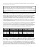
Table 2 NovaRoam™ 900 Channels
Channel Frequency (MHz)
Mode Minimum Maximum
1 906 924
2 906 924
3 906 924
4 909 921
5 909 921
6 909 921
7 909 921