
User's Manual
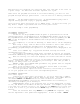
transformer is now wired. Replace the transformer cover and the two screws. DO
NOT turn on power yet.
NOTE: Failure to ground unit properly may cause severe damage to the controller
and/or personal property and will void warranty.
Figure 1 goes here Pudik see page 6 EZ manual
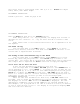
For models 8674, 8676, 8678, 8682, 8686, 8690, 8694 (see figure 2)
Remove the transformer cover by loosening the two screws. Route AC wires
to connector provided. Cut and trim wires to install in chassis mount connector.
Tighten the screws. (For Australia an extra clamp has been provided.) Observe
proper polarity of wires as you install them (ie. L1, L2 and ground). The
transformer is now wired. Replace the transformer cover and the two screws. DO
NOT turn on power yet.
NOTE: Failure to ground unit properly may cause severe damage to the controller
and/or personal property and will void warranty.
Figure 2 goes here Pudik see page 7 EZ
INSTALLATION INSTRUCTIONS
Terminal Strip
All zone, pump and sensor wire connections made inside the EZ Pro utilize
tool-less connectors. Pull the lever into the upper position and insert the
wire into the bottom. Push the lever down to lock in the wire. The terminal
strips in the EZ Pro controller accept 14 AWG (1.6mm) wire or smaller.
Connecting Master Valve or Pump-Start Relay
The EZ Pro is equipped with a shared circuit to operate either a pump-
start relay or a master valve. Connect one wire from the pump-start relay to
COM (common) on terminal strip, the other to PMP/MV (pump/master valve) on the
terminal strip. Refer to the pump-start relay manufacturer’s instructions for
specific installation details.
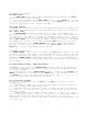
Connecting Rain/Moisture Sensor
The EZ Pro is equipped to operate a sensor with normally-closed leads.
The sensor port on the EZ Pro is the first tool-less connector on the
interconnect board (see Figure 2). To install a sensor, remove the factory-
installed jumper wire from the sensor connector on the terminal strip and insert
the sensor wires. Refer to the sensor manufacturer’s instructions for specific
installation details. (See figure 2)
If a sensor has suspended watering, the sensor indicator segment will
appear on the LCD. The symbol will go off when the sensor has dried out. The EZ
Pro will resume operation based on the selected program.
INSTALLATION INSTRUCTIONS
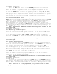
Connecting the batteries and starting the controller
Remove the battery access door from the rear panel. Insert two new AA
Alkaline (LR6 in Europe) batteries to the battery clips and install the battery
access door. The batteries enable the EZ Pro to be programmed without AC power
and maintain the real time clock in the event of a power outage. If the