
User's Manual

• Four start times per program (12 total starts)
• Stacking start times
• Three scheduling options to suit the needs of plant material or to comply with watering
restrictions (days of the week, 1-30 day interval, true odd / even )
• Leap year compatible-automatically includes Feb 29
th
every four years
• Water budget option reduces or increases watering 0-200 percent
• Advanced water budget to set water budget for each month of the year
• Three test cycles ( Manual with ManualAdvanceTM feature,Cycle, 3-minute test
• Programmable run times from one minute to 9 hours 59 minutes
• Poly-fuse self resetting circuit protection
INSTALLATION INSTRUCTIONS
The EZ Pro can be mounted indoors or outdoors. Find a location near a
120V wiring source (230/240V for 8674, 8676, 8678, 8682, 8686, 8690, and 8694
models). Install the EZ Pro near eye level if possible. Use the supplied
template to mark and pre-drill pilot holes in the wall. The middle two hole
guides in the EZ Pro are vertically aligned for mounting the controller to a
stud. (See Template) Insert screws through the holes in the case and screw each
into the corresponding pilot hole in the wall.
NOTE: The front panel can be removed to aid in installation by removing
the ribbon connector from the interconnect board and pulling the front panel off
its hinges.
"IMPORTANT NOTE For Radio models: To comply with FCC RF exposure compliance requirements, the following antenna installation and device
operating configurations must be satisfied - The antenna used for this transmitter must be installed to provide a separation distance of at least 20 cm from
all persons and must not be co-located or operating in conjunction with any other antenna or transmitter."
Wiring the Transformer
120 VAC in United States, Canada and Mexico; 230 VAC in Europe and 240 VAC
in Australia
NOTE: Refer to and follow local codes if different from these
instructions.
CAUTION: Disconnect 120V (230/240V for 8674, 8676, 8678, 8682, 8686, 8690,
and 8694 models) power source before wiring transformer. Complete all wiring
and installation before connecting the transformer to power source. This will
avoid accidental shorting which could damage the controller.
Power supply cables and cords used for connections are to be a minimum of
ordinary duty or greater duty. Live supply wires should be attached together
adjacent to the terminal block. Low voltage output cables should be enclosed in
conduit affixed to the controller with a suitable adapter. Remove the two screws
and lift out the transformer cover to provide access to the internal
transformer, bring 120V (or 230/240 for 8674, 8676, 8678, 8682, 8686, 8690,8694)
wires up through 1/2" conduit hole in the bottom of the case. (For field
connection, AC wires must have an insulation rated at 75°C minimum). Conduit
should be secured to the case (follow local codes).
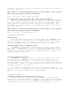
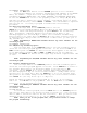
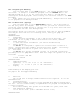
For models 8604, 8606, 8608, 8612, 8616, 8620, 8624 (see figure 1)
Remove the transformer cover by loosening the two screws. Attach AC wires
to transformer wires using wire nuts. Also, ensure earth ground wire is
attached to green with yellow stripe ground wire. Please check local codes for
the grounding requirements in your area. Bundle wire within cable tie loop and
tighten cable tie to prevent loose wiring from touching secondary circuits. The