
Manual

IP-00021 Rev. A – 03/04 Page 1/2
INSTALLATION INSTRUCTIONS: HG2418P
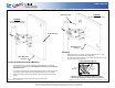
Open Drain Hole
on bottom
Figure B
Horizontal Pol
arized Positi
on
Drain Hole Plug
Figure A
Vertical Polarized Position
(As shippe
d from factory
)
Open Drain Hole
on
botto
m
Drain Hole Plug
Mounting
1.
Mount the ante
nna as sho
wn,
ens
uring U-Bol
t
nuts are securely
tightened to prevent antenna shift in high wind.
2. The antenna can be mounted in a up or down tilt position from 0-60°.
See below for mounting options.
L-Bracket Mounting Options
Vertical or Horizontal Polarized Mounting
1. T
h
is antenna can be vertica
l p
o
larized mounted (Figure A) o
r
horizontal
polarized moun
ted (F
igure B). It is shipped from the factory in the vertical
po
larized position.
2.
To mount the an
tenna i
n the horizonta
l polarized positi
on, rotate antenna i
nto
the position shown in Figure B. Note
orienta
tion label on rear of antenna.
3. Remove the drain hole pl
ug from curr
ent location and replace into position
shown.
4. Attach antenna to L-Bracket using the (4) pan head screws.
Fixed
Mounting
20°
30°
0°
10°
40°
50°
60°
Var
i
ab
le
Mounting
0°-60°
Fixed 0° Mounting
L-Bracket shown for down-tilt mounting. For up-tilt,
rotate b
r
ack
et 180 de
g
rees when attach
ing
to antenn
a.
www.L-com.com
Copyright © This drawing is property of L-com Global Connectivity. All rights reserved.
L-COM, INC. 45 BEECHWOOD DRIVE NORTH ANDOVER, MA 01845
WWW.L-COM.COM E-MAIL: SALES@L-COM.COM PHONE: 1-800-343-1455 FAX: 1-978-689-9484
© L-com, Inc. All Rights Reserved. L-com Global Connectivity and the L-com logo are registered marks.