
User Manual


Tube Heater Specifications
4
AT100 AT125 AT150
30 40 40 50 50
120 150 150 180 180
140 170 170 200 200
100,000 125,000 150,000
65,000 75,000 90,000
4.63 5.79 7.09
100 125 150
13.5 in. W.C., L.P. and Natural Gas
11.0 in. W.C., L.P. Gas
7.0 in. W.C., Natural Gas
10.0 in. W.C., L.P. Gas
4.0 in. W.C., Natural Gas
4.5 in. W.C., L.P. Gas
2.0 in. W.C., Natural Gas
140 CFM
Ball Bearing
1/30 H.P., 3020 RPM, CW Rotation
115/60/1
STARTING 1.16
CONTINUOUS
OPERATION
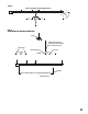
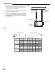
TOP
1 ft.
SIDES 6 ft.
DISCHARGE END 6 ft.
BELOW RADIANT TUBES 6 ft.
12-18 in. Above Litter and Approx. 15 Ft. Down from Burner Box
Ventilation Air Required
to Support Combustion
Minimum Safe
Distances of Heater
From Nearest
Combustible Materials
(See Fig. 1 on page 5)
Amp Draw
(Starting Amps
Include Igniter)
Motor Characteristics
1.02
Temperature Sensor Location
(See Fig. 2 on page 5)
SPECIFICATIONS
Models
Inlet Gas Supply
Pressure Acceptable
at the Inlet of the
Heater for Purpose of
Input Adjustment
Maximum Input per Hour (BTUH)
Minimum Input per Hour (BTUH)
(Two Stage Gas Control)
Available Tube Lengths (ft.)
MAIN IN SINGLE STAGE CONTROL
SECOND STAGE IN TWO
STAGE CONTROL
FIRST STAGE IN TWO
STAGE CONTROL
MAX.
MIN.
Burner
Manifold
Pressure
Fuel Consumption
per Hour (Max.)
Electrical Supply (Volts/Hz/Phase)
Net Weight (lbs.)
Shipping Weight (lbs.)
L.P. GAS (lbs.)
NAT. GAS (cu. ft.)
4.0 in. W.C., L.P. Gas
1.8 in. W.C., Natural Gas