Owner’s Manual and Instructions SENTINEL® Agricultural Building Radiant Tube Heaters MODELS AT 150 AT 125 AT 100 OUTPUT (Btuh) 150,000 125,000 100,000 FUEL Propane Vapor Withdrawal or Natural Gas Congratulations! You have purchased the finest radiant tube heater available for the heating of poultry confinement buildings. Your new L.B. White radiant heater incorporates the benefits from the most experienced manufacturer of heating products using state-of-the-art technology. We, at L.B.
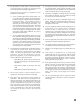
GENERAL HAZARD WARNING ■ Failure to comply with the precautions and instructions provided with this heater, can result in: — Death — Serious bodily injury or burns — Property damage or loss from fire or explosion — Asphyxiation due to lack of adequate air supply or carbon monoxide poisoning — Electrical shock ■ Read this Owner’s Manual before installing or using this heater. ■ Only properly-trained service people should repair or install this heater. ■ Save this Owner’s Manual for future use and reference.
Table of Contents PAGE SECTION General Information . . . . . . . . . . . . . . . . . . . . . . . . . . . . . . . . . . . . . . . . . . . . . . . . . . . . . . . . . . . . . . . . . . .3 Heater Specifications . . . . . . . . . . . . . . . . . . . . . . . . . . . . . . . . . . . . . . . . . . . . . . . . . . . . . . . . . . . . . . . . . .4 Safety Precautions . . . . . . . . . . . . . . . . . . . . . . . . . . . . . . . . . . . . . . . . . . . . . . . . . . . . . . . . . . . . . . . . . . . .
Tube Heater Specifications Models AT100 SPECIFICATIONS AT125 AT150 Available Tube Lengths (ft.) 30 40 40 50 50 Net Weight (lbs.) 120 150 150 180 180 Shipping Weight (lbs.) 140 170 170 200 200 Maximum Input per Hour (BTUH) 100,000 125,000 150,000 Minimum Input per Hour (BTUH) (Two Stage Gas Control) 65,000 75,000 90,000 L.P. GAS (lbs.) 4.63 5.79 7.09 NAT. GAS (cu. ft.) 100 125 150 Fuel Consumption per Hour (Max.
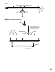
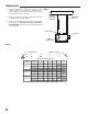
FIG. 1 SAFE CLEARANCES FROM COMBUSTIBLES 6 FT FT 61 IN 6 FT 6 FT 6 FT 6 FT 6 FT FIG. 2 TEMPERATURE SENSOR LOCATION HEATER SENSOR LOCATED DIRECTLY ABOVE INSIDE WATER LINE AND OR IN PROXIMITY SENSOR 12-18 IN. ABOVE THE LITTER INSIDE TOWATER AN IN LINE WATER LINES FEED LINE INSIDE WATER LINE FEED LINE LITTER " 12-18 IN. SENSOR INSTALL SENSOR APPROX.
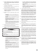
Safety Precautions WARNING Asphyxiation Hazard ■ Do not use this radiant heater for heating human living L.B. White Company to determine combustion air quarters. ventilation requirements of the heater. ■ Do not use in unventilated areas. ■ The flow of combustion and ventilation air must not be obstructed. ■ Proper ventilation must be provided to support the combustion air requirements of the heater being used.
1. Do not attempt to install, repair, or service this heater or the gas supply line unless you have continuing expert training and knowledge of gas heaters. Qualifications for service and installation of this equipment are as follows: a. To be a qualified gas heater service person, you must have sufficient training and experience to handle all aspects of gas-fired heater installation, service and repair.
Installation Instructions GENERAL 1. Read all safety precautions and follow L.B. White recommendations when installing this heater. If during the installation of the heater, you suspect that a part is damaged or defective, call a qualified service agency for repair or replacement. 2 A qualified service agency must check the heater upon installation and periodically. This shall consist of the following: c. locations where wind and/or the elements can create a negative pressure.
5. Heater installation must take into consideration proper hanging height to allow for clearance of catching machines, litter spreaders, and any other equipment used. -- -6. Ensure the heater installation does not interfere with water, gas, or electrical lines. -- 7. Position the gas hose to prevent any contact with the tubes, heat relectors, and burner box. -- 8. Ensure that all accessories that ship with the heater have been removed from shipping containers and installed.
INITIAL SETUP 1. Plan the installation. Determine location for the heater to optimize its heat pattern, keeping in mind cooler regions in the house (end walls, and curtains) and clearances to combustibles. FIG. 5 JOIST OPEN EYE HOOKS IN LINE WITH EYE BOLTS ON BURNER BOX 2. Hang the burner box. See Fig. 5. Maintain clearances to combustibles as shown in Fig. 1. TIGHTEN HOOKS SECURELY 3. From the burner box chain, measure the distances shown in Fig. 6.
HANGING THE TUBES Refer to Fig. 7 and the following instructions: 3. Slide on hangers and connect to chains. 1. Slide a tube clamp over the non-swaged end of 10 ft. aluminized tube. (One aluminized tube per kit.) 4. Connect and hang remaining tubes. F ollow the procedures given in Step 2. 2. Install the tube over the swaged discharge tube on the burner box. 5. The tube assembly should be either hung level, or with a downward slope away from the burner box not exceeding 1 in. for every 10 ft. of tube.
INSTALLING REFLECTORS & SUPPORTS Refer to Fig. 8 for the following instructions: 1. Attach end cap to non-notched end of a reflector. Use 4 U-clips. 2. Slide the reflector through the hangers until end cap is up against burner box. 4. Attach remaining end cap to last reflector with U-clips. 5. Install a support at end of reflector nearest burner box,and at middle and ends of all reflectors. Do not install a support directly next to a hanger on the same reflector. 3. Slide remaining reflectors over tubes.
AIR TURBULATION STRIPS & VENT HOOD Assemble the strips and insert into last tube. Edge of strip is flush with end of tube. See Fig. 9. Refer to Fig.10 for installation of vent hood. FIG. 10 FIG. 9 TUBE VENT HOOD PUSH VENT ONTO PUSHHOOD FIRMLYFIRMLY ONTO END TUBEEND OF LAST TUBE, OUTLET DOWN. FLAPPER OF VENT HOOD MUST CLOSE COMPLETELY. OUTLET END OUTLET END INSERT STRIP ASSEMBLY INTO LAST 10INSERT FT.
HEATER CONTROLS Refer to the heater’s burner box hinged access panel, or refer to Start-up instructions in this manual to determine if your heater has a single or two stage gas control. 3 Building Controller Connections (See Fig.15) -- Remove wire nut from yellow and orange wires. -- Connect controller contacts as shown. FIG. 15 WARNING Electrical Shock Hazard ■ Disconnect the heater’s electrical supply before interconnecting the temperature control.
Start-Up Instructions Follow steps 1 - 6 on initial start-up after heater installation. For normal start-up, simply turn thermostat above room temperature. The heater will start. 1. FIG. 19 Open all manual fuel supply valves and check for gas leaks using approved leak detectors. The gas control valve has a manual shut-off feature incorporated into the valve assembly. Ensure the indicator on the valve is turned to the ON position. See Fig. 18. RED FIG. 18 AMBER BURNER VIEWING WINDOW 6. 2.
Cleaning Instructions WARNING Fire, Burn, and Explosion Hazard ■ This heater contains electrical and mechanical components in the gas management, safety and airflow systems. ■ Such components may become inoperative or fail due to dust, dirt, wear, aging, or the corrosive atmosphere of an animal confinement building. ■ Periodic cleaning and inspection as well as proper maintenance are essential to avoid serious injury or property damage. 1.
Maintenance Instructions 1. Have your gas supplier check all gas piping annually for leaks or restrictions in gas lines. Also, at this time have your gas supplier clean out the sediment trap on the zone control panel of any debris that may have accumulated. 6. If any warning or instruction labels, dataplates, etc. become lost or hard to read, replace them immediately. Do not operate the heater until you have all instructions and can read and understand them. 2.
IGNITER The tip of the igniter is exposed to a harsh environment consisting of high temperatures and combustion products. Periodic servicing is required. B. MAINTENANCE 1. Remove igniter from burner box. Ensure the gap is 1/8 in. See Fig. 22. 2. Clean the electrode and ground rod using emery cloth. A. REPLACEMENT 1. Remove igniter mounting screws. See Fig. 20. 2. Remove ignition cable from igniter. See Fig. 21. FIG. 22 FIG. 20 1/8 IN. SCREWS ELECTRODE FIG.
BURNER ORIFICE 1. Remove the igniter FIG. 25 2. Remove the clear flexible tube from the pressure switch. Fig.24. . 3. Remove the four nuts from the burner mounting studs and remove burner . See Fig.24. ORIFICE FIG. 24 MANIFOLD TUBE 5. When reinstalling the burner, ensure larger opening between burner vanes is directed to the access door of the burner box. See Fig.26 .FIG. 26 NUTS LARGER OPENING 4 Securely hold the burner manifold in place while removing the orifice from the manifold. See Fig. 25.
AIR DIFFERENTIAL PRESSURE SWITCH, TUBING & PRESSURE ORIFICES For proper heater operation: ■ The copper pressure tube at the burner vane must be straight. See Fig.31. ■ Ensure the clear flexible tube is free of dust and securely connected to the fitting at the burner and to the fitting at the differential pressure switch. See Figs. 32. ■ The air differential pressure orifices should be free of blockages. If cleaning is required use pressurised air: Orifices on pressure switch (See Fig.
Gas Pressure Checks ■ The following is a typical procedure to be followed in FIG. 33 checking gas pressures for single or two stage gas control valves ■ Consult the dataplate on the heater or page 4 in this manual for specific pressures. The gas pressures will vary depending upon fuel type. CONNECTOR ■ Gas pressure measured at the inlet to the gas valve is Inlet Pressure and gas pressure measured at the outlet of the gas valve is Burner Manifold Pressure.
4. If the inlet pressure is correct but the burner manifold pressure does not agree with that specified on the dataplate, then the pressure regulator internal to the gas control requires adjustment. Refer to the following instructions. The burner box will need to be opened and closed/latched as needed to accurately set the gas control pressures. Single Stage Gas Controls Set the thermostat to its highest setting. The single amber light on the burner box panel will come on, and gas control will open.
Troubleshooting Information READ THIS ENTIRE SECTION BEFORE BEGINNING TO TROUBLESHOOT PROBLEMS. WARNING ■ This heater can start at any time. ■ Troubleshooting this system may require operating the unit with line voltage present and gas on. Use extreme caution when working on the heater. ■ Failure to follow this warning may result in property damage, personal injury or death. The following troubleshooting guide provides procedures for isolating equipment problems.
Red LED not on during a call for heat. Problem No Is proper voltage supplied to heater power cord and through power cord? No Does heater start? Replace ignition control. Poor electrical connection or broken wire present. Repair or replace. Voltage drop from thermostat to terminal W on ignition control. Incorrect wire size from thermostat to terminal W on ignition control. No Yes Set thermostat above room temperature.
Two Times Differential air pressure switch contacts have not closed. Indicates no air proving in fan section of heater One Time Differential air pessure switch contacts are closed before fan motor starts. Red LED Flashing Yes No Is fan loose on motor shaft? No Is burner box gasketing torn, or missing? No Is pressure switch stuck open? Check continuity. Yes Yes Yes Defective wire or loose connection to air pressure switch.
Five Times Four Times Lockout from too many flame losses. Three Times Ignition failure. The control module is in safety lockout. -- Defective Wires or Connections, Repair or Replace. -- Defective Ignition Control Module. No Are 24 volts supplied to gas control valve? No If control module does not reset, then replace it. (Internal board fault.) If module resets, then have qualified electrician check power source for power quality problems.
Electrical Connection and Ladder Diagram SINGLE STAGE THERMOSTAT & GAS CONTROL 27
TWO STAGE THERMOSTAT & GAS CONTROL HI 28 LO
Heater Component Function Burner Cast iron component used to channel gas and provide an area at which the fuel may ignite. Gas Hose Flexible connector used to convey gas from supply line in building to heater. Burner Orifice Brass metering device used to feed gas to burner at a specific rate. Igniter Ignition device used on automatic direct spark ignition control systems. Ignites gas by spark. Burner Tubes Conducts the heat provided by the ignition of fuel gas at the burner.
Parts Identification PARTS SCHEMATIC 51 34 48 33 31 50 49 33 35 50 36 47 39 37 38 50 4 5 41 42 43 44 25 24 3 31 45 2 32 52 23 28 22 26 20 46 30 11 1 27 13 29 15 21 5 6 19 18 14 12 16 40 10 7 8 30 9
PARTS LIST Item 1 2 3 4 5 6 7 8 9 10 11 12 13 14 15 16 17 18 19 19A 19B 20 21 22 23 24 25 26 27 29 30 31 32 33 34 35 36 37 38 39 40 41 42 43 44 45 46 47 48 49 50 51 52 NOTE: AT100 Description Air Turbulation Strip Vent Hood Tube, Uncoated, 4 in. x 10 ft. Tube, Aluminized, 4 in. x 10 ft.
Warranty Policy HEATER L.B. White Co., Inc. warrants that the component parts of its heater are free from defects in material and workmanship, when properly installed, operated, and maintained in accordance with the Installation and Maintenance Instructions, safety guides and labels contained with each unit. If, within 12 months from the date of purchase by the end user, any component is found to be defective, L.B. White Co., Inc.