Owner's Manual and Instructions GUARDIAN® Agricultural Animal Confinement Building Heater MODELS AB250 OUTPUT (Btuh) 250,000 FUEL Available in either L.P. Gas Vapor Withdrawal or Natural Gas Configurations. Certification by: * Specific models are certified by C.S.A. International. Contact L.B. White co. for further information. Congratulations! You have purchased the finest agricultural building heater available. Your new L.B.
GENERAL HAZARD WARNING ■ Failure to comply with the precautions and instructions provided with this heater, can result in: — Death — Serious bodily injury or burns — Property damage or loss from fire or explosion — Asphyxiation due to lack of adequate air supply or carbon monoxide poisoning — Electrical shock ■ Read this Owner’s Manual before installing or using this product. ■ Only properly-trained service people should repair or install this heater. ■ Save this Owner’s Manual for future use and reference.
Table of Contents SECTION PAGE General Information . . . . . . . . . . . . . . . . . . . . . . . . . . . . . . . . . . . . . . . . . . . . . . . . . . . . . . . . . . . . . . . . . . .3 Heater Specifications . . . . . . . . . . . . . . . . . . . . . . . . . . . . . . . . . . . . . . . . . . . . . . . . . . . . . . . . . . . . . . . . .4 Safety Precautions . . . . . . . . . . . . . . . . . . . . . . . . . . . . . . . . . . . . . . . . . . . . . . . . . . . . . . . . . . . . . . . . . . . .
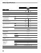
Heater Specifications Model AB250 SPECIFICATIONS L.P. Gas Natural Gas Maximum Input (BTUH) Minimum Input (BTUH) 250,000 160,000 Ventilation Air Required to Support Combustion 1,050 CFM Inlet Gas Supply Pressure Acceptable at the Inlet of the Heater for Purpose of Input Adjustment 11.5 in. W.C. 7 in. W.C. 10 in. W.C. 4 in. W.C. MAX. 11.57 lbs. 250 cu. ft. MIN. 7.41 lbs. 160 cu. ft. MIN. Burner Manifold Pressure Fuel Consumption Per Hour 13.5 in. W.C. MAX.
Safety Precautions WARNING ■ ■ ■ ■ ■ Asphyxiation Hazard Company to determine combustion air ventilation Do not use this heater for heating human living quarters. requirements of the heater. Do not use in unventilated areas. ■ Lack of proper ventilation air will lead to improper combustion. The flow of combustion and ventilation air must not be obstructed. ■ Improper combustion can lead to carbon monoxide poisoning in humans leading to serious injury or death.
interior of the heater and it’s components. After external washdown, do not operate this heater until it is completely dry. In any event, do not operate the heater for at least one hour after external washdown. 1. Do not attempt to install, repair, or service this heater or the gas supply line unless you have continuing expert training and knowledge of gas heaters. Qualifications for service and installation of this equipment are as follows: a.
Installation Instructions GENERAL WARNING Fire or explosion hazard. Can cause property damage, severe injury or death. 1. Disconnect power supply before wiring to prevent electrical shock or equipment damage. 2. To avoid dangerous accumulation of fuel gas, turn off gas supply at the heater’s service valve before starting installation, and perform gas leak test after completion of installation. 3. Do not force the gas control knob. Use only your hand to turn the gas control knob. Never use any tools.
12. Ensure the heater has the proper gas regulator for the application. A regulator must be connected to the gas supply so that gas pressure at the inlet to the gas valve is regulated within the range specified on the dataplate at all times. Contact your gas supplier, or the L.B. White Co., Inc. if you have any questions. 13. This heater can be configured for use with either L.P. gas vapor withdrawal or natural gas.
HANGING INSTRUCTIONS 1. Assemble according to the illustration and tighten all eyebolts securely. (See Fig. 2): FIG. 3 NOTE: REGULATORS SHOULD ALWAYS BE MOUNTED OUTDOORS. IF CIRCUMSTANCES FORCE INSTALLING THE REGULATOR INDOORS, THE REGULATOR'S VENT MUST BE VENTED OUTDOORS USING VENT LINE NO SMALLER THAN VENT OPENING. FIG.
THERMOSTAT INSTALLATION WARNING Electrical Shock Hazard ■ Disconnect the electrical supply before connecting the thermostat to the heater. ■ Failure to follow this warning can result in electrical shock, leading to personal injury or death. 1. To Connect the Series Tap Plug Thermostat Kit: a. Connect the power cord of the heater to the female side of the plug on the end of the thermostat cord. b.
Start-Up Instructions Follow steps 1 - 8 on initial start-up after heater installation by a qualified gas heater service person. For normal startup, simply turn thermostat above room temperature. The heater will start. 1. Open all manual fuel supply valves and check for gas leaks using approved certified leak detectors. 2. The gas control valve incorporates a manual gas shut off feature. Position the indicator on the shut off knob to pilot. 3.
Variable Heat Output 1. Some models of propane (LP) gas or natural gas heaters have a throttle valve for varying heat output located between the gas control valve and gas manifold assemblies. THIS IS NOT A MANUAL GAS SHUT OFF VALVE. 2. The throttle valve can be adjusted to deliver either minimum heat or maximum heat. When the throttle valve handle is parallel to the gas flow, the valve is FIG. 7 completely open to deliver maximum heat output. (Refer to Fig. 7.
Cleaning Instructions WARNING Fire, Burn, and Explosion Hazard ■ This heater contains electrical and mechanical components in the gas management, safety and airflow systems. ■ Such components may become inoperative or fail due to dust, dirt, wear, aging, or the corrosive atmosphere of an animal confinement building. ■ Periodic cleaning and inspection as well as proper maintenance are essential to avoid serious injury or property damage. 1.
Electrical Connection and Ladder Diagram CAUTION Always refer to the heater’s electrical connection diagram when servicing to avoid wiring errors and heater malfunction. Check for proper operation after servicing.
Heater Component Function Air Proving Switch Safety device used to insure that the proper air flow is being achieved before the gas valve is opened. Pilot Light Orifice A metering device used to supply gas for the dual purpose of igniting the main burner and heating the thermocouple. Burner Cast iron component used to channel gas and provide an area at which the fuel may ignite.
Parts Identification Parts Schematic 33 37 36 38 34 40 35 33 39 41 32 42 31 30 29 43 27 26 1 24 28 16 23 15 22 14 21 20 2 25 19 18 3 7 13 12 17 5 11 44 4 10 9 8 6 16
Parts List Item 1 2 3 4 5 6 7 8 9 10 11 12 13 14 15 16 17 18 19 20 21 22 23 24 25 26 27 28 29 30 31 32 33 34 35 36 37 38 39 40 41 42 43 44 Description Regulator, Second Stage (LP Gas) Regulator, Second Stage (Nat. Gas) Nipple, 3 1/2 in. Valve, Manual Shut-Off Hose, 1/2 in. x 10 ft.
Warranty Policy EQUIPMENT L.B. White Co., Inc. warrants that the component parts of its equipment are free from defects in material and workmanship, when properly installed, operated, and maintained in accordance with the Installation and Maintenance Instructions, safety guides and labels contained with each unit. If, within 12 months from the date of purchase by the end user, any component is found to be defective, L.B. White Co., Inc.