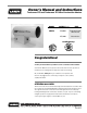
Owner's Manual and Instructions Tradesman 170 and Tradesman 170 Ultra Construction Heaters MODEL OUTPUT (Btuh) CP170 FUEL 170,000 Propane Vapor Withdrawal 155,000 Natural Gas Certification by: Congratulations! You have purchased the finest portable forced air construction heater available. Your new L.B. White heater incorporates the benefits from the most experienced manufacturer of heating products using state-of-the-art technology. We, at L.B.
GENERAL HAZARD WARNING ■ Failure to comply with the precautions and instructions provided with this heater, can result in: — Death — Serious bodily injury or burns — Property damage or loss from fire or explosion — Asphyxiation due to lack of adequate air supply or carbon monoxide poisoning — Electrical shock ■ Read this Owner’s Manual before installing or using this product. ■ Only properly-trained service people should repair or install this heater. ■ Save this Owner’s Manual for future use and reference.
Table of Contents SECTION PAGE General Information . . . . . . . . . . . . . . . . . . . . . . . . . . . . . . . . . . . . . . . . . . . . . . . . . . . . . . . . . . . . . . . . . . .3 Heater Specifications . . . . . . . . . . . . . . . . . . . . . . . . . . . . . . . . . . . . . . . . . . . . . . . . . . . . . . . . . . . . . . . . . .4 Safety Precautions . . . . . . . . . . . . . . . . . . . . . . . . . . . . . . . . . . . . . . . . . . . . . . . . . . . . . . . . . . . . . . . . . . . .
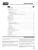
Heater Specifications SPECIFICATIONS Model CP170 Propane Gas Fuel Type Maximum / Minimum Input (BTUH) Burner Manifold Pressure (in. W.C.) Inlet Gas Supply Pressure Acceptable at the Gas Connection of the Heater. (in. W.C.) Natural Gas 170,000 /125,000 155,000/125,000 11.0 5.5 MAX. 11.1 13.5 MIN. 11.1 7.0 Fuel Consumption Per Hour MAX. 7.87 lbs. 155 cu. ft. Sleeve Bearing Motor Characteristics 1/15 H.P., 3,200 RPM Electrical Supply (Volts/Hz/Phase) 115/60/1 STARTING Amp Draw 3.
Safety Precautions WARNING Asphyxiation Hazard ■ Do not use this heater for heating human living quarters. ■ Lack of proper ventilation air will lead to improper combustion. ■ Do not use in unventilated areas. ■ Improper combustion can lead to carbon monoxide poisoning leading to serious injur y or death. Symptoms of carbon monoxide poisoning can include headaches, dizziness and difficulty in breathing. ■ The flow of combustion and ventilation air must not be obstructed.
WARNING Burn Hazard ■ High surface and discharge temperatures. ■ Do not touch the heater or come within safe clearances given on dataplate. ■ Use extreme caution when lighting the heater or adjusting heat levels. ■ Failure to follow this warning and come too close to the heater can result in burns or ignition of clothing. ■ Burns cause serious injury or death. 1.
Installation and Assembly Instructions GENERAL WARNING Fire and Explosion Hazard Can cause property damage, severe injury or death To avoid dangerous accumulation of fuel gas, turn off gas supply at the heater service valve before starting installation, and perform gas leak test after completion of installation. 1. Read all safety precautions and follow L. B. White recommendations when installing this heater.
12 Make sure the heater has the proper gas regulator for the application. A regulator must be connected to the gas supply so that gas pressure at the inlet to the gas valve is regulated within the range specified on the dataplate at all times. Contact your gas supplier, or the L.B. White Co., Inc. if you have any questions. 16. Eventually, like all electrical/mechanical devices, the thermostat can fail. Thermostat failure may result in an underheating condition.
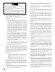
HOSE AND REGULATOR ASSEMBLY Propane Gas 1. Connect rigid end of hose to regulator and tighten securely. FIG. 2 2. Install hose adapter to gas inlet of heater. Tighten adpater securely. Connect end of hose with nut to hose adapter. Tighten hose nut securely. See Fig 3. FIG. 3 Natural Gas -- Connect the components and regulator at the heater’s gas inlet as shown in Fig. 4. Ensure flow arrow on regulator body is in direction of gas flow. Tighten all securely. FIG.
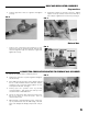
HEIGHT ADJUSTMENT This heater includes a height adjustment feature, allowing the user to change the elevation of the heater for greater heat direction. See Fig. 6 for location of adjustment on front base of heater. FIG. 6 KNOB To adjust the heater’s discharge outlet height: -- Loosen knob -- Lift heater slightly at blower outlet end -- Pull leg to desired setting -- Tighten knob. WARNING Burn Hazard ■ Do not adjust height while heater is operating or hot.
Start-Up Instructions 1. Connect the heater’s electrical cord to an approved electrical outlet. 2. Open the gas supply valve. For LP heaters, this is located on the cylinder or tank. 3. Set thermostat on heater to a setting above room temperature. The heater will start and the burner will ignite. ■ It is normal for air to be trapped in gas hose on new installations. You may need to recycle the heater before air is finally purged from the line and ignition takes place. 4.
Cleaning Instructions WARNING Fire, Burn, and Explosion Hazard ■ This heater contains electrical and mechanical components in the gas management, and safety systems. ■ Such components may become inoperative or fail due to dust, dirt, wear and aging. ■ Periodic cleaning and inspection as well as proper maintenance are essential to avoid serious injury or property damage. 1. Before cleaning, shut off all gas supply valves and disconnect electrical supply. 2.
Service Instructions GENERAL WARNING Burn Hazard ■ Heater surfaces are hot for a period of time after the heater has been shut down. ■ Allow the heater to cool before performing service, 4. Remove the fan guard and motor/fan assembly for access to barrel components. 5. The auto reset limit switches, and thermostat can be tested by disconnecting the leads at the component, and placing a jumper connecting the leads together.: maintenance, or cleaning.
AUTO RESET LIMIT SWITCHES There are two auto reset limit switches on this heater. One is located on the burner plate. The other is located on the underside of the combustion chamber. Either will cut off power to the gas control valve if the heater should overheat. FIG. 11 P Switch mounted on burner plate. See Fig. 10. -- Remove the screws, spacers and nuts holding the switch to the burner plate. N FIG. 10 NUTS,SCREWS, SPACERS HEIGHT ADJUSTMENT LEG TESTING The switches should be tested annually.
IGNITER MAINTENANCE 1. 2. REMOVAL Using a small wire brush, reach down the barrel of the heater and brush the igniter electrode. Remove any build up. 1. Disconnect the ignitIon cable from the igniter. See Fig.16. FIG. 16 Periodically check the gap. Gap should be 3/16 as shown in Fig. 15. FIG. 14 IGNITION CABLE MOUNTING NUT IGNITOR ELECTRODE MOUNTING SCREW 2. Remove the igniter mounting screw and nut. See Figs. 14 and 16. FIG. 15 3/16 in. BURNER ORIFICE 1.
THERMOSTAT 1. Remove knob and thermostat mounting screws. See Fig. 19. 2. Remove the base bottom from the heater. 3. Slide the thermostat sensing bulb from the cable tie at the wiring harness.See Fig. 20. FIG. 20 FIG. 19 BULB THERMOSTAT SCREWS IGNITION CONTROL 1. Disconnect the LED wire harness from the circuit board, if applicable. 2. Disconnect the ignition cable and remove the nuts securing the control to the side of the heater’s base. See Fig. 21. 3.
GAS PRESSURE CHECKS ■ The following explains a typical procedure to be followed in checking gas pressures. ■ The gas pressures will vary depending upon fuel type. ■ Consult the dataplate on the heater or page 4 in this 3. Position the heater upright. Lower the height adjustment leg to elevate the heater and prevent pinching of gauge hose See Fig. 24. FIG. 24 manual for specific pressures to be used in conjunction with this procedure.
Troubleshooting Information READ THIS ENTIRE SECTION BEFORE BEGINNING TO TROUBLESHOOT PROBLEMS. WARNING ■ This heater can start at any time. ■ Troubleshooting this system may require operating the unit with voltage present and gas on. Be careful when working on the heater. ■ Failure to follow this warning may result in property damage, personal injury or death. The following troubleshooting guide provides systematic procedures for isolating equipment problems.
No Does fan motor run? No Is proper voltage supplied to heater power cord? No Does thermostat receive proper voltage from power cord? Does heater light? Is air proving switch shorted? (Check continuity on air proving switch in open and closed positions). No Yes No Is air proving switch Yes Repair. binding? If air proving switch is jumered, remove jumper and retest. If switch exhibits short, replace the switch.
Two Times Indicates lack of air proving in fan section (Flash pattern begins within 90 seconds after condition Occurs). Problem Yes Replace motor Defective Yes ignition control. Check circuit breakers, and any extension cords if used. Contact a qualified electrician No Is proper voltage supplied to heater power cord? No Is ignition control receiving proper voltage? No Is proper voltage supplied to motor from ignition control? No Does fan motor run? Yes Yes Yes Repair.
Problem Five Times Rapid On/Off cycling of the burner. Four Times Three Times Indicates ignition failure.The ignition control is in safety lockout.. 21 Yes Yes Defective gas valve. Yes Connect high voltage lead No Is igniter high voltage lead securely connected? No Does ignitor spark? Connect proper gas supply to heater. Open all gas shutoff valves. No No Yes Yes Flame sense related problems.
Heater lights but will not stay lit. No Is proper voltage Yes supplied to heater? Connect high voltage lead? No Is high voltage lead securely connected? Ensure all grounds are connected. No Is the heater properly grounded? Yes Connect proper gas supply to heater. Open all gas shutoff valves. No Yes No Yes No Does fan motor start? Check electrical supply. If extension cords are used, ensure proper wire gauge. No Yes Clean and check gap.
Defective wires or connections. If good, replace ignition control. No Is proper voltage supplied to valve? No Does gas solenoid valve open? Fan runs, heater does not light. Problem Defective valve. Yes Yes Yes Yes Yes Yes No Are the backflash switch contacts closed? Yes Yes Check the burner orifice for blockage. Clean or replace the orifice . Reposition igniter.
Electrical Connection and Ladder Diagrams TRADESMAN 170 ULTRA TRADESMAN 170 CAUTION - REFER TO THE HEATER'S ELECTRICAL CONNECTION DIAGRAM WHEN SERVICING TO AVOID WIRING ERRORS & HEATER MALFUNCTION. CHECK FOR PROPER OPERATION AFTER SERVICING.
Heater Component Function Air Proving Switch Safety device used to insure that the proper air flow is being achieved before the gas valve is opened. Gas Control Solenoid Valve House an electromagnet which is energized by voltage and opens to allow passage of gas to the burner orifice. Auto Reset Limit Switch Safety device wired into the control system which is used to break an electrical circuit to the gas control valve in event of overheat situation.
Parts Identification PARTS SCHEMATIC 26
PARTS LIST Item 1A 1B 2 3A 3B 4 5 6 7 8 9 10 11 12 13 14 15 16 17 18 19 20 21 22 23 24 25 26 27 28 29 30 31 Description Part Number Tradesman 170 Tradesman 170 ULTRA Regulator with POL (Propane Gas) Regulator (Natural Gas) Hose, Fixed X Swivel, 3/8 in. x 10 ft. (Propane gas ) Hose, Fixed X Swivel, 1/2 in. x 10 ft. (Natural gas) Accessory Adaptor, Hose, 3/8 in. (Propane Gas) Adaptor, Hose, 1/2 in.
Warranty Policy EQUIPMENT L.B. White Co., Inc. warrants that the component parts of its heater are free from defects in material and workmanship, when properly installed, operated, and maintained in accordance with the Owner’s Manual safety guides and labels contained with each unit. If, within 12 months from the date of purchase by the end user, any component is found to be defective, L.B. White Co., Inc. will at its option, repair or replace the defective part or heater, with a new part or heater, F.O.B.