
Install Manual

Preliminary
SKY899
Installation Manual
A-2
Rev. A
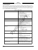
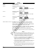
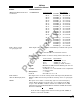
SIGNAL CHARACTERISTICS
Antenna Top Directional SUM (SIGMA) Port (Blue)
CONNECTION Connector
Signal Name
J9 - TNC SUM
CABLE Cable attenuation must not exceed 2.5 dB, VSWR
1.5:1. Refer to paragraph 2.6.1.
Impedance: 50 Ω
Antenna Top Directional BIT PROBE Port (Black)
CONNECTION Connector
Signal Name
J10 - BNC BIT
CABLE Cable attenuation must not exceed 6 dB, VSWR
1.5:1. Refer to paragraph 2.6.1.
Impedance: 50 Ω
Antenna Top Directional DIFFERENCE (DELTA) Port (Red)
CONNECTION Connector
Signal Name
J11 - TNC DIFFERENCE
CABLE Cable attenuation must not exceed 2.5 dB, VSWR
1.5:1. Refer to paragraph 2.6.1.
Impedance: 50 Ω
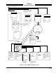
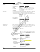
ARINC-429 External Interface The SKY899 has seven ARINC-429 receivers and three transmitter
(paragraph 2.9). Four of the channels are paired internally and can
operate at either low speed (12.5 kHz) or high speed (100 kHz). However,
the paired channels must be set to the same speed (see tables A-1 and A-
2). The transmitters operate only at high speed (100 kHz).
The first ARINC-429 transmitter (A429TX1) is intended to provide the
capability to interface with alternate display device. The second and third
ARINC-429 transmitters (A429TX2 & TX3) are a future option.
Five of the ARINC-429 receivers can be used to input data from other
avionics systems. The sixth and seventh receivers are not used at this time
(future option).
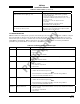
NOTES
1. The radio altimeter must provide full range output between 0 and
2500 feet. Not all altimeters provide this full range output. The full
range output can sometimes be obtained as a mod to the radio
altimeter . Check with the specific altimeter manufacturer for
compatibility and availability of modification, if necessary.
2. The TRC can accept Radio Altimeter input from ARINC-429 or DC
analog source. The Barometric Altitude can be ARINC-429 or
Gilham Code. The Magnetic Heading can be ARINC-429 or Synchro
(XYZ). Select only one source for each aircraft input.
3. If 429 barometric altitude is used, it should be from the same source
that is interfaced with the transponder or it must be at least as
accurate as that source, i.e., ± 125 ft.
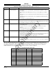
4. Receive channels 1 and 2 must be set to the same speed (12.5 or 100
kHz). Receive channels 3 and 4 must be set to the same speed (12.5
or 100 kHz). Channel 5 is independent of the other receivers and
can be to 12.5 or 100 kHz.