
Install Manual

Preliminary
SKY899
Installation Manual
4-21
Rev. A
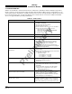
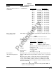
Table 4-1. Fault Isolation (Continued)
SYMPTOM CORRECTIVE ACTION
SKY899 paints itself as a target (e.g., TA). a. Verify suppression bus shielded cable is grounded
correctly at both ends.
b. Connect an oscilloscope to the suppression bus and
verify that the SKY899 suppression pulse (100 µs ±5 µs)
exceeds +15 V dc.
c. If less than +15 V dc, the suppression bus is
overloaded.
d. Check all equipment connected to the bus.
e. Repair/replace the offending device.
SKY899 TRC899 has been removed for service; the WX-
1000
Stormscope
fails to operate.
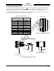
Check the adapter plug (see para 4.7). If the TRC899 is
removed for service, an adapter plug is required to permit
continued operation of the WX-1000.
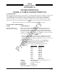
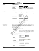
4.6 ERROR MESSAGES
SKY899 firmware is designed to generate error messages associated with a particular condition or step in
the program. The 20 most recent errors detected by the system are saved in the System Log (see para
4.4.2.2). For your convenience, in table 4-2, we have listed the error messages that have been associated
with SKY899 installations. Where appropriate, procedures that may assist in resolving installation
problems are provided. When a severe error occurs SKY899 will fail.
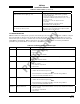
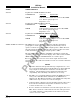
Table 4-2. Installation Related Error Messages
ERROR NO. MESSAGE REMARKS
ERROR 06 I2C Bus Error a. Configuration module is present, however the BUS communication (SDA or SCL) is
incorrect check associated wiring.
b. Replace TRC.
c. Replace configuration module.
ERROR 07 Config Module Error a. Configuration module is not found check associated wiring.
b. Replace TRC.
c. Replace configuration module.
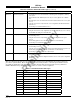
ERROR 10 Compact Flash Error a. Unable to read the compact flash information correctly, verify compact flash is inserted
into J12 correctly.
b. Try a different compact flash.
c. Replace TRC.
ERROR 14 RF Amplitude Error a. Check directional antenna and associated cables.
b. Calibrate directional antenna (para 4.4.3)
NOTE
Ensure transponder is in standby and DME is OFF while doing calibration
c. Cycle power and run pilot initiated self-test.
ERROR 15 RF Angle Error a. Check directional antenna and associated cables.
b. Calibrate directional antenna (para 4.4.3)
NOTE
Ensure transponder is in standby and DME is OFF while doing calibration
c. Cycle power and run pilot initiated self-test.
ERROR 17 Mag Var Table Error a. Unable to read the compact flash information correctly, verify compact flash is inserted
into J12 correctly.
b. Try a different compact flash.
c. Replace TRC.