
Install Manual

Preliminary
SKY899
Installation Manual
4-20
Rev. A
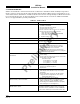
4.5 TROUBLESHOOTING
Table 4-1 is intended to assist trained electronic technicians to determine which assembly is inoperative.
Do the corrective action steps in the order described. Use the Service Menu (refer to paragraph 4.4) as an
aid in fault isolation. Information available from the service menu can help identify conditions that need to
be resolved. If interfaced to an alternate display service menu must be accessed via an RS-232 terminal
device, see Appendix E for operating instructions.
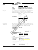
Table 4-1. Fault Isolation
SYMPTOM CORRECTIVE ACTION
Display remains dark after SKY899 is powered ON.
a. Check position of the WX-1000 maintenance switch
(NORMAL/OVERRIDE).
b. Reset circuit breaker if it is tripped.
c. Check aircraft power source.
d. Check connection to WX-1000 processor, if installed.
e. Check power input at TRC mating connector.
P8-A +28V (18 - 32 V dc PWR)
P8-B +28V_RET (AIRCRAFT PWR RETURN)
f. Check cables connected to display.
g. Replace Display.
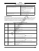
Display is distorted.
Check for interference from aircraft systems.
Incorrect response to buttons (soft-keys).
Check soft-key wiring inside display cable and WX-1000
processor cable (if installed).
SKY899 will not enter service menu.
a. Check soft-key wiring.
b. If using an alternate display device the soft-key's
needed for accessing service menu from the WX-
1000/SKY497 display are not connected.
c. If using an alternate display service menu must be
accessed with an RS-232 terminal device by typing the
menu command. (Appendix E)
The self-test successfully completes without audio
annunciation.
a. Check headphones/speaker and aircraft audio panel
switch settings.
b. Check volume level and run audio test in service menu.
c. Check cables connected to TRC.
Audio Alert Output:
P1-89 (AUDIO_H - 600-Ohm)
P1-90 (AUDIO_L - 150-Ohm)
P1-91 (AUDIO_C - Common)
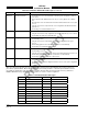
SKY899 Failed.
a. Check system log (para 4.4.2) for errors. Error
messages are detailed in para 4.6.
b. Replace TRC.
Self-test does not execute. Aircraft is on the ground.
a. If standby screen is displayed, check soft-key wiring
inside display cable and WX-1000 processor cable
(if installed).
b. Check squat switch connection to the TRC and the
weight-on-wheels configuration in service menu.
Squat Switch Input: P1-24
The display cannot be switched between SKY899 and the
WX-1000. Both systems are installed.
a. Check circuit breakers. Reset if tripped.
b. Check position of the WX-1000 maintenance switch
(SW2). It should be set to the NORMAL position.
c. Check wiring of the SKYWATCH/
Stormscope
display
mode switch (para 2.7.3 and figure 2-2).
WX-1000 processor has been removed for service;
SKY899 fails to operate.
Check position of the WX-1000 maintenance switch
(NORMAL/OVERRIDE). When the WX-1000 has been
removed for service, it should be set to the OVERRIDE
position. This switch may be located in the avionics bay.