
Install Manual

Preliminary
SKY899
Installation Manual
3-7
Rev. A
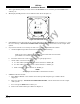
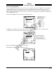
14. From each test point (see step 12):
a. Position the TT391 Patch Antenna facing the SKYWATCH HP aircraft under test.
b. Set the TT391 POWER switch to the ON position.
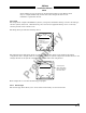
c. Verify that the display shows, in the direction (± 30 degrees) of the TT391, two targets; a Traffic
Advisory (i.e., a solid circle) at ¼ nm and Other Traffic (i.e., open diamond) at 4.5 nm. Both
targets will be displayed in level flight at own aircraft altitude (i.e., "00" displayed above the
traffic symbol).
NOTES
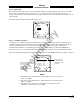
1. If the display reflects a gross error in target bearing, check the directional
antenna cables at TRC connectors J9 (sum port) and J11 (difference port).
They may be reversed. A further indication of this condition would be a
target that moved in a counter-clockwise direction when the TT391 is
moved in a clockwise direction.
2. Multiple targets or a faulty bearing may result from multipath distortion
(see step 1).
3. During these tests, the SKY899 may detect and display other active
targets.
4. To obtain a better line of sight, it may be necessary to elevate the patch
antenna.
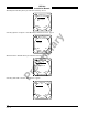
d. Set the TT391 POWER switch to the OFF. Repeat procedure from each test point. Step 15 can
be done from the last test point.
NOTE
To prevent SKYWATCH HP from tracking the movement of the test-set, it is
necessary to set the TT391 POWER switch to OFF after completing each
bearing measurement.
15. Return the TT391 assemblies to their position in the aluminum carrying case.
16. Restart SKY899 by cycling power OFF and then ON.
17. Connect an oscilloscope to the suppression bus and verify that the SKY899 suppression pulse (100 µs
±5 µs) exceeds +15 V dc. If less than +15 V dc the suppression bus is overloaded. Check all equipment
connected to the bus. Repair/replace the offending device.
18. This completes the post installation checkout procedure.
3.4 SELF TEST
1. Turn SKY899 OFF and then:
a. Make sure the aircraft's transponder is in the STANDBY, ON, or ALT mode.
NOTE
After power up, it may take a couple of minutes for the altitude encoder to
return a valid altitude to the transponder and SKY899.
b. If installed, power up the radio altimeter.
c. Make sure all compass/HSI flags are cleared from the aircraft's instruments.
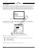
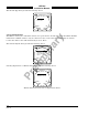
2. Turn SKY899 ON. The display should show a start-up screen similar to one shown in figure 3-2.