
Install Manual

Preliminary
SKY899
Installation Manual
3-5
Rev. A
3.3.2 System Setup Verification and Operation
1. Turn ON all avionics equipment interfaced to the SKY899.
2. From the Service Menu (see paragraph 4.4), select Information.
3. From the Information menu, select Data Monitor. The Data Monitors menu will appear.
4. Select each of the data monitors and verify the sensor information is correct (see paragraph 4.4.2.3):
a. Change the status of the landing gear, squat switch, altitude, and heading sensors.
Verify data monitors show the correct input changes (i.e., sensing of these signals).
b. If the information is not correct, the sensor has failed to communicate with the TRC. Check
operation of the sensor and connections between the TRC and sensor.
c. Select exit until you return to the Service Menu.
5. From the Service Menu, select Ground Test (see paragraph 4.4.4).
6. From the Ground Test menu, select Perform Ground Test.
7. Verify operation of range function. Soft-key (3) is labeled to indicate the current range. Press soft-key
(3) to toggle the display range between 2, 6 and 15 nm.
8. Select the 6 nautical mile range.
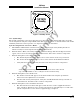
9. Verify that the system toggles through the altitude display modes. Soft-key (2) is labeled to indicate
the current mode. Press Soft-key (2) to select normal (NRM), below (BLW), above (ABV), and
unrestricted (UNR).
10. Select the NRM (normal) mode.
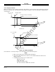
11. Position the aircraft with the nose aligned on any 90 degree heading. Avoid areas within 250 ft of
obstructions (e.g., hangers, large aircraft, control towers, etc.) where there is a potential for multipath
problems. Locate and mark test points at 30 degree intervals (i.e., 000, 030, 060, 090, 120, 150, 180,
210, 240, 270, 300, and 330 degrees) with respect to the directional antenna. Mark these points at the
same distance, between 100 and 150 ft, from the aircraft.
12. Position the TT391 Flightline Tester on one of the test points identified in previous step.
CAUTION
The Flightline Tester is not weatherproof when the lid is open. Do not setup
or operate the Flightline Tester in conditions of rain, sleet, etc.
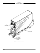
13. Setup and verify operation of the TT391 Flightline Tester:
a. Open the chassis lid and remove the lid from the chassis by sliding the lid off of the hinge pins
(sliding it to the right). The lid "stay" must be removed from the lid before mounting. The stay
will pop off of the lid. (The stay is the hinged part that props the lid open on the chassis).
NOTE
The Patch Antenna may be used without a tripod. The Patch Antenna can be
held, or secured, and pointed towards the SKYWATCH HP aircraft under test
WITH THE MOUNTING STUD POINT TOWARD THE GROUND. This orientation is
critical.
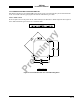
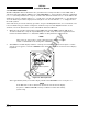
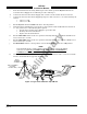
b. Mount the chassis lid, with the Patch Antenna facing the aircraft, onto a tripod (not included).
The tripod must be capable of holding the antenna (approximately 2.5 lb) and must provide a
standard base mounting stud threaded 1/4"-20. A typical tripod mount is shown in figure 3-4.