
Install Manual

Preliminary
SKY899
Installation Manual
2-33
Rev. A
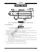
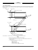
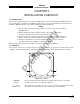
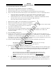
Figure 2-13. Mounting Holes for Ruggedized Mounting Tray, P/N 805-10870-003
2.26 TRC INSTALLATION
CAUTION
Before placing the TRC into its mounting tray, de-energize or disconnect all
power and signal sources and loads used with the SKY899 system.
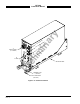
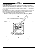
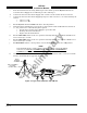
1. Slide the TRC into the mounting tray (see figure 2-14). Ensure that the rear hold-down pins on the
mounting tray are properly inserted into receptacles on the TRC.
2. Place the retainer cups over the TRC J-hooks. Secure the TRC to the mounting tray by tightening the
self-locking hold-down knobs.
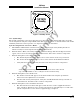
3. Connect the three antenna inputs to the connectors on the front panel.
a. Connect the Sum port antenna connector (P9 - a TNC connector identified with a blue band) to
connector J9 (identified with blue marking).
b. Connect the Probe (Bit) port antenna connector (P10 - a BNC connector identified with a black
band) to connector J10.
c. Connect the Difference (Delta) port antenna connector (P11 - a TNC connector identified with a
red band) to connector J11 (identified with red marking).
4. Connect I/O Signal Cable (P1 - a 100-pin connector) to connector J1.
5. Connect the power cable (P8 - a three-pin connector) to connector J8.