
Install Manual


Preliminary
SKY899
Installation Manual
2-30
Rev. A
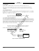
2.23 WX-1000 PROCESSOR (OPTIONAL)
The SKYWATCH HP can be interfaced to the Stormscope weather mapping system. The connections are
listed in table 2-3.
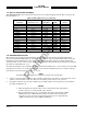
Table 2-3. WX -1000 Processor Connection
WIRE COLOR
FUNCTION WX-1000 Processor SUB-CABLE WIRE TRC899
SHIELD P301-5
PWRSWHI P301-21 GREEN WHITE SW2*
PWRSWLO P301-20 GREEN BLUE SW2*
+15 P301-3 WHITE WHITE P1-25
-15 P301-36 WHITE ORANGE P1-26
DSPGND P301-38 WHITE BLUE P1-27
HSYNCHI P301-6 WHITE BLUE P1-28
HSYNCLO P301-23 BLUE WHITE P1-29
VSYNCHI P301-40 ORANGE WHITE P1-30
VSYNCLO P301-7 ORANGE BLUE P1-41
VIDEOHI P301-22 RED BLUE P1-35
VIDEOLO P301-39 RED WHITE P1-36
SFTKEY1 P301-9 BLACK WHITE P1-37
SFTKEY2 P301-26 BLACK BLUE P1-38
SFTKEY3 P301-43 YELLOW WHITE P1-39
SFTKEY4 P301-44 YELLOW BLUE P1-40
*SW2 required if WX-1000 Processor installed (see figure 2-2).
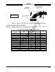
2.24 ANTENNA INSTALLATION
The following paragraphs provide installation details for directional antenna. Standard installation
practices prescribed in FAA Advisory Circular No. 43.13 must be followed. The installer must ensure the
immediate antenna installation area is clean and prepared so that the antenna is electrically bonded
(metal-to-metal contact) to the aircraft. To provide optimum bonding through the mounting holes, prepare
the surfaces with Alodine No. 1001.
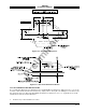
To facilitate mounting to the airframe, the dimensions shown in Figure 2-10 can be used to locate and drill
mounting and connector access holes. Connection to the antenna should be made in accordance with the
system interconnect diagram (figure 2-2, 2-3 or 2-4).
NOTE
A doubler plate (not supplied) is required to reinforce the aircraft skin.
1. Connect each of the three antenna cables. Check to ensure that each cable is connected to the correct
antenna connector. Each connector/cable has a matching color band (see note par.2.6.1).
2. Attach the antenna to the aircraft, with the special adapter plate and o-ring, using 10-32 hardware
provided. See Figure 2-11.
NOTES
1. When mounting the antenna remove the O-ring from the bag and install it
in the O-ring groove on the bottom of the antenna.
2. For pressurized aircraft, use a sealant that meets the requirements of SAE
AMS-S-8802 such as Flamemaster CS3204 class B. For non-pressurized
aircraft, use a non-corrosive sealant that meets the physical requirements
of MIL-A-46146 such as General Electric RTV162.