
Install Manual


Preliminary
SKY899
Installation Manual
2-28
Rev. A
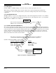
2.19 SOFT-KEYS
If using a WX-1000/SKY497 display connect the soft-keys 1 thru 4 per figures 2-2 or 2-3.
When using an alternate display device reference figure 2-4 as well as manufacturer instructions
concerning these connections. Required soft-key connections will depend upon the alternate display
capabilities.
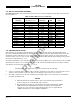
2.20 SUPPRESSION BUS I/O
The TRC outputs a 100 µs (± 5 µs) suppression pulse on the aircraft suppression bus (P1-93). In addition,
the TRC899 receives suppression signals from all other devices on the suppression bus (e.g., transponder,
DME). (Reference ARINC 735-2 and DO-197.)
CAUTION
The aircraft transponder must have suppression circuitry to ensure that
SKY899 does not paint itself as a target (e.g., TA).
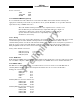
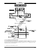
2.21 SYSTEM CONFIGURATION MODULE
The system configuration module (figure 2-8) is used to store aircraft installation dependent information
(e.g., aircraft type, discrete inputs, heading source, speed of data bus, etc.). Aircraft specific information is
selected via the service menu, typically during system setup. Once the setup settings have been saved the
system configuration will stay with the aircraft wiring allowing the TRC to be replaced or exchanged
without having to re-configure the TRC. When powered up the configuration information is sent to the
TRC via the bi-directional serial data bus (SDA).
NOTE
The system configuration module must be located inside the backshell of
connector P1 and wire-tied to the bundle of wires. Reference figure 2-9.
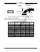
System Configuration Module connections:
System Configuration Module TRC899
Red (VCC) -to- P1-2 (+3.3V)
Black (Ground) -to- P1-92 (PLUG_GND)
Green (Serial Clock) -to- P1-100 (SCL)
Yellow (Serial Data) -to- P1-99 (SDA)
RED
TO P1-2 (+3.3V)
TO P1-92 (PLUG_GND)
TO P1-100 (SCL)
TO P1-99 (SDA)
CONFIG MODULE
P/N 814-18005-001
BLACK
GREEN
YELLOW
TERMINAL
P/N M39029/56-348
Figure 2-8. System Configuration Module