
Install Manual

Preliminary
SKY899
Installation Manual
2-22
Rev. A
NOTE
If the aircraft is not equipped with a squat switch, it is recommended that a
squat switch be installed.
Squat switch connection:
SQUAT P1-24
If a squat switch is not available, this input could be tied to an airspeed switch inline with the pitot system
as an alternate input for the squat switch. In this configuration care should be taken to ensure the switch
is set to trigger at a speed consistent with take-off and landing.
On helicopter installations with skids, and a squat switch is not available, this input can be tied to the
collective switch. In this configuration care should be taken to ensure the switch is connected to provide a
ground when the aircraft is on the ground and open when the aircraft is airborne.
If it is not possible to install a squat switch, airspeed switch, or collective switch, select none in service
menu. With this configuration the pilot must toggle the system in and out of standby manually. Traffic
will only be displayed when the pilot switches out of the standby position.
With a squat switch installed, SKYWATCH HP will automatically switch out of standby 8 to 10 seconds
after takeoff and switch back to standby 24 seconds after landing. A squat switch would also prevent the
pilot from placing SKYWATCH HP in standby (i.e., pressing the →
→→
→STB button) while the aircraft is in-
flight.
2.7.5
ON/OFF
Power Switch
This input connection turns the TRC ON and OFF. Wiring of this input will vary depending upon your
specific installation. With pin P1-4 connected to P1-5 the system will turn on. There are three possible
configurations discussed below:
Alternate Display. A separate ON/OFF switch is required (any SPDT toggle switch rated at 3A @ 28 V dc
can be used). Refer to display manufactures instructions and figure 2-4 concerning this connection.
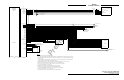
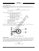
WX-1000/SKY497 Display (without WX-1000). Connect per figure 2-2.
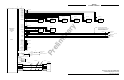
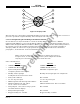
Stormscope WX-1000 Installation. This external over-ride switch (SW2) is required if a WX-1000
Stormscope Weather Mapping System is installed. The override switch enables the SKYWATCH HP to be
powered-up if the WX-1000 processor has been removed for maintenance. During normal operation the
switch should remain in the NORMAL position and moved to OVERRIDE only if the WX-1000 processor
has been removed for service or if it is necessary to access the WX-1000 service menu. Connect per figure
2-3
Any general purpose DPDT toggle switch (3 Amp @ 28 V dc) may be used. The maintenance switch cable
routing and length are not critical to system operation. The switch can be located in the avionics bay near
the WX-1000 processor.
ON/OFF power switch connection:
ON/OFF P1-4
ON/OFF_RET P1-5
2.8 ALTERNATE DISPLAY
Alternate display (ARINC-735 compatible is required for TCAS I installation) is connected to ARINC-429
output channel. Refer to paragraph 2.9 for ARINC-429 output channel information.